Warning
You are reading the documentation for an older Pickit release (2.3). Documentation for the latest release (3.3) can be found here.
Connect the cables
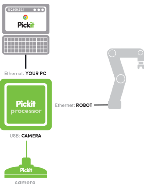
In this step, we will connect all the cables to the Pickit processor. Note that all the ports on the back of the Pickit processor are correctly labeled. See the image below for an overview of all necessary connections. Follow the steps below to connect the processor:
Connect the processor to the power outlet with the provided cable.
Connect the Pickit M or L camera with the 10 m USB cable (CBL-USB-CAM-10) and plug it into the CAMERA labeled USB port at the back side of the Pickit processor. When the Pickit camera is connected correctly, a continuous green light is lit on front of the Pickit camera. In case of an M-HD camera, the power supply must be connected to the camera as well.
Warning
A USB hub is not allowed between the Pickit processor and camera connection.
Connect the gray/black 5 m UTP network cable (CBL-CAT6-GRAY-5 / CBL-CAT6-BLACK-5) from your computer to the YOUR PC labeled RJ45 port on the Pickit processor.
Connect the green 5 m UTP network cable (CBL-CAT6-GREEN-5) from your robot or machine controller with the ROBOT labeled RJ45 port at the back side of the Pickit processor.
Tip
The last step, the connection to a robot, is not necessary to already test the Pickit system.
Tip
More information about connecting all the hardware components can be found in Connecting the cables.