Warning
You are reading the documentation for an older Pickit release (2.0). Documentation for the latest release (3.4) can be found here.
How to execute robot camera calibration
Pickit provides two methods of executing this calibration. Which method to choose depends on how Pickit is set up and how it will be used.
If the Pickit camera is fixed to an independent structure, Multi poses calibration and Single pose calibration can be used depending on the setup.
If the Pickit camera is mounted on the robot, only Multi poses calibration can be used.
The first steps in the calibration process are:
Selecting the camera mounting type for your application
Choosing calibration method
Warning
Wrong or old calibration parameters can lead to unexpected motions. Safe motions of the robot must always be checked by the operator of the robot itself and can never be guaranteed by Pickit.
Multi poses calibration
Camera fixed to an independent structure
Clamp the calibration plate to the robot flange or end-effector in whatever way you can but always make sure the plate is rigidly attached to the flange during the calibration process. You can Installing the Pickit calibration plate, grab it firmly with a gripper, screw it to a tool or any other way that it is firmly attached to the robot flange or end-effector.
Find five robot poses that are sufficiently different and that still allow the camera to see the calibration plate.
Next step: Calculate multi poses calibration.
Camera mounted on the robot
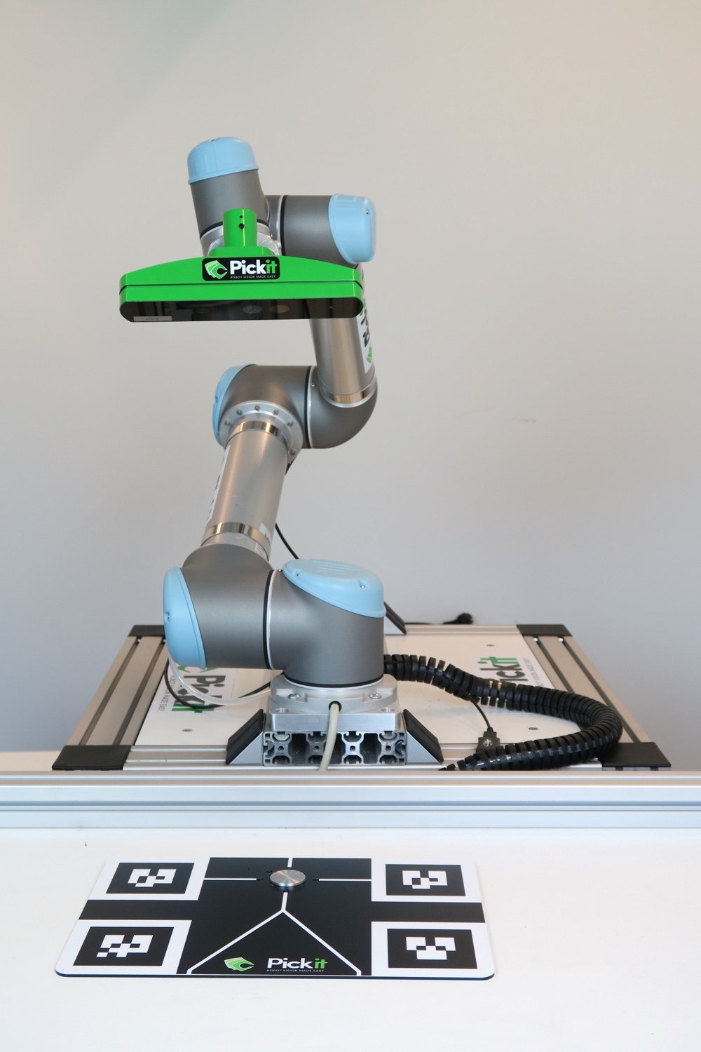
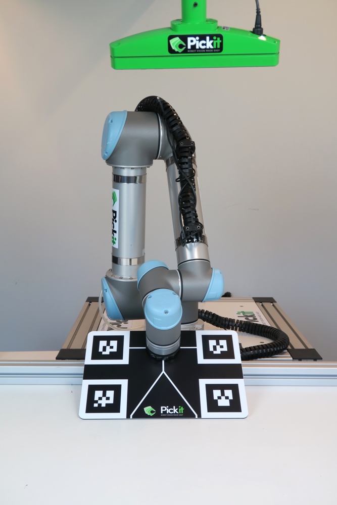
Place the calibration plate in front of the robot in the center of the region for picking. Make sure the plate cannot move during the calibration process.
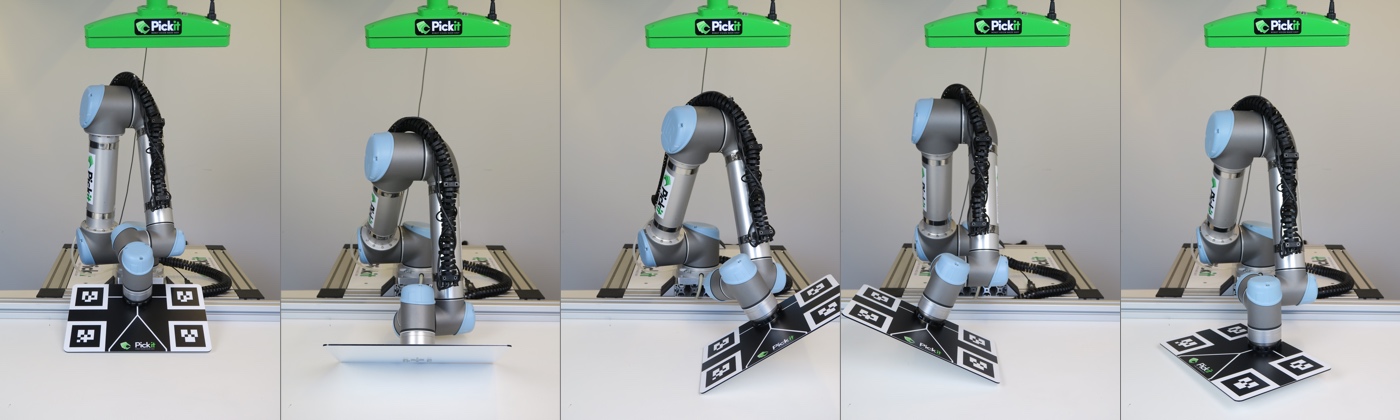
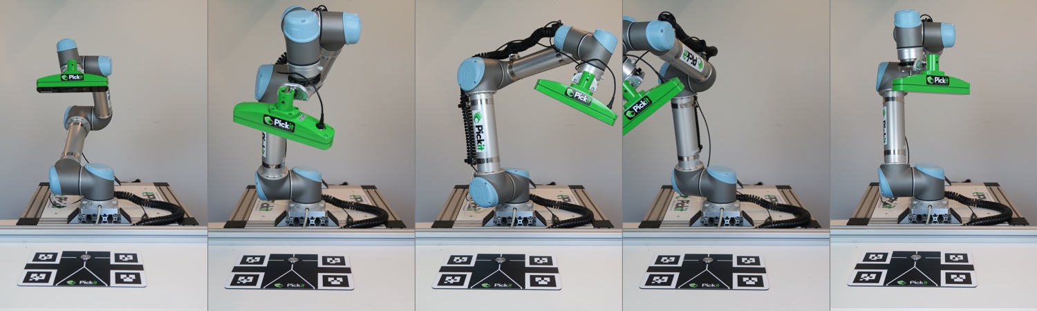
Find 5 robot poses (Top, North, East, South, West) that are sufficiently different and that still allows the camera to see the calibration plate. Preferably, the calibration plate is as much as possible in the center of the region where the actual picking will take place.
Next step: Calculate multi poses calibration.
Calculate multi poses calibration
Go to the Calibration tab in the Pickit web interface and select Multi Poses Calibration.
Now repeat the following cycle for every pose:
Move the robot to the first pose for calibration.
At this point, a request for calibration should be sent.
This request should be sent from the robot using the provided calibration program. This program can be found under the Files tab of the Pickit web interface or shipped by the respective robot integration.
After each successful collection of such a pair of transformations, the interface looks as follows:
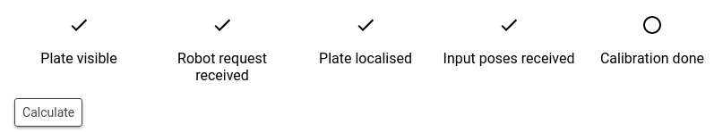
When this cycle has been done for the 5 poses, click the Save button.
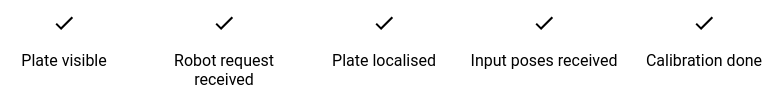
At the end of the calibration process, all indicators should have a checkmark. If they do not, consult the log window for instructions.
If something went wrong in the middle of the calibration process, you can always restart from the beginning by pressing the Reset poses button.
Note
Always Verify calibration in the 3D view as shown below.
Single pose calibration
Some restrictive conditions on using single pose calibration
Single pose calibration can only be executed when the camera is not mounted on the robot.
Single pose calibration can only be executed on robots with a certain type of flanges, namely with 50 mm (ISO 9409-1-50-4-M6) and 31 mm (ISO 9409-1-31.5-4-M5) wide flanges.
The calibration plate has to be mounted in a way the position and orientation of the calibration plate with respect to the robot flange is exactly known and later configured in the Pickit system.
If one of these conditions can not be met, you will need to perform calibration with Multi poses calibration.
Step 1: Install calibration plate
Go to the Calibration tab of the Pickit user interface and select Single pose calibration.
Mount the calibration plate to the robot flange directly or by making use of a tool changer of your choice. Read more on Installing the Pickit calibration plate.
Position the robot such that the calibration plate can be seen by the camera (the “Plate visible” indicator should be green). Preferably, the calibration plate is as much as possible in the center of the region where the actual picking will take place.
Step 2: Define helper transformation
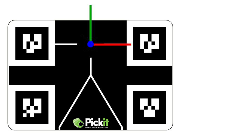
The helper transformation is the transformation between the flange frame of the robot and the calibration plate frame. On the figure below you can see the defined calibration plate frame.
The helper transformation from the robot flange to the calibration plate results from the following possible motions:
a possible rotation around the Z-axes
a possible translation along Z-axes
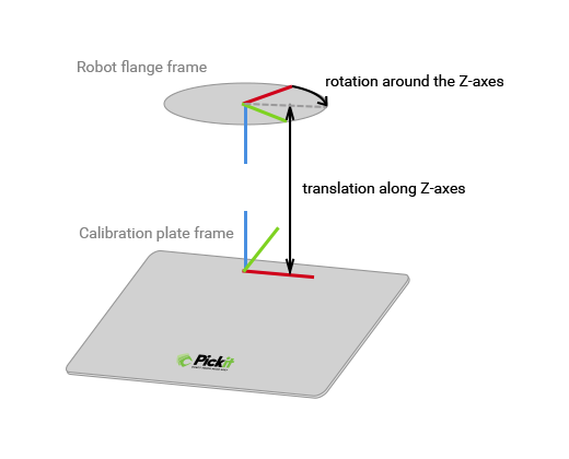
If the calibration plate is mounted directly to the robot flange, the translation will always be 0. If something (a tool, a tool changer, …) is in between the calibration plate and the robot flange the translation will not be 0.
All robot brands and types can have varying helper transformations but here you can find some examples for the case that the calibration plate is mounted directly to the robot flange:
Universal Robots: UR3, UR5 and UR10: translation: 0 | rotation: 45°
Fanuc: LR Mate: translation: 0 | rotation: 135°
KUKA: KR16: translation: 0 | rotation: -45°
Staubli: 0 | 135°
ABB: 0 | -45°
Yaskawa: 0 | -45°
Step 3: Send a calibration request from the robot
At this point, a request for calibration should be sent.
This request should be sent from the robot using the provided calibration program. This program can be found under the Files tab of the Pickit web interface or on the downloads page.
Once Pickit receives the request for calibration from the robot the robot-camera calibration is calculated.
At the end of a successful calibration, all indicators should be green. If they do not turn green, consult the log window for instructions.
Note
Always Verify calibration in the 3D view as shown below.
Verify calibration
Verify the result of the calibration in the 3D view, by looking at the robot_base frame and the camera frame locations and their relative positions. It is recommended to have a look from different viewpoints to verify that the position and orientation of the robot_base frame look correct.
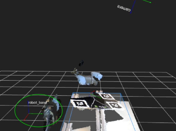
SAVE the new calibration to the current setup file when it looks correct. Redo calibration if the result does not look correct.
At this point, calibration is done!
The calibration parameters are stored on the Pickit processor. Recalibration is only required when the camera is moved or rotated with respect to the robot.
Universal Robots
If you have a Universal Robots robot, you can additionally visualize a virtual 3D robot, which should make it easier to verify the correctness of calibration. To do so, follow these steps:
Make sure Pickit is communicating with the robot: a Pickit robot program is running and the Robot status indicator at the top of the web interface shows a checkmark. .. image:: /assets/images/Documentation/Communication-robot.png
Navigate to the 3D view and click on the View settings button on the lower right of the viewport. .. image:: /assets/images/Documentation/Settings-button.png
Toggle the visualize Robot check mark. .. image:: /assets/images/Documentation/Visualize-robot.png
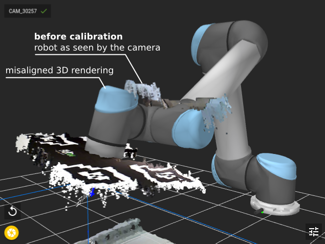
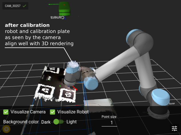
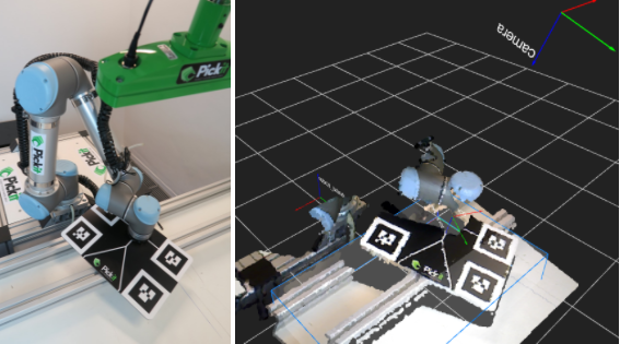
This allows you to intuitively check whether the virtual 3D robot aligns well with the displayed coordinate frames and captured point cloud. For example, the following images show a fixed-camera scenario where the robot is inside the camera view volume. It can be seen how, before calibration, the robot as seen by the camera does not align with the virtual 3D robot. After calibration they nicely align. Similarly, the attached calibration plate (only visible to the camera, not part of the virtual 3D robot) is correctly aligned with respect to the robot flange after calibration.