Hole
Overview
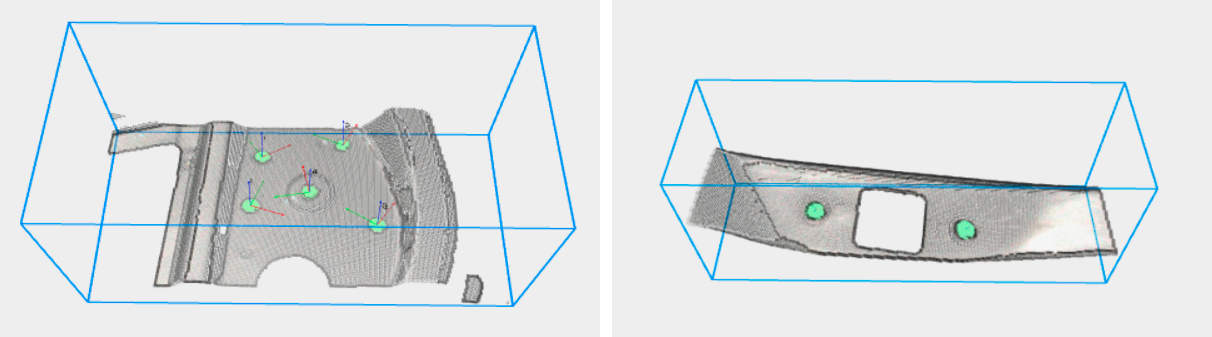
Pickit Hole is a detection engine for detecting circular holes of known size on a surface. With an HD camera, it can detect holes as small as 6mm in diameter, which makes it a good choice for screwing and assembly applications.
This detection engine is an optional add-on that can be added to a Pickit system by means of a license module. Please get in touch with the Pickit sales team to learn more.
Detection parameters
The hole detection engine has the following configuration parameters:
Hole diameter: Size of the hole to detect.
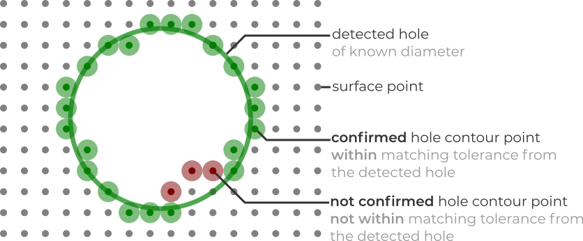
Minimum matching score: Percentage of hole contour points to be confirmed for a detection to be valid.
Matching tolerance: Allowed deviation between hole and contour points.
Maximum hole fill rate: Maximum percentage of the hole allowed to be filled (by surface and contour points) for a detection to be valid.
Hole detection refinement
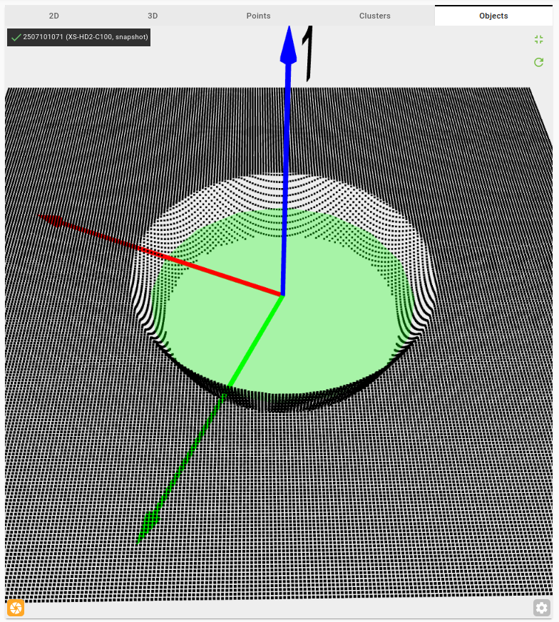
The hole refinement step is an optional extension of the hole detection engine that improves hole detection accuracy and enables detecting inner holes. Inner holes are holes that are set back from the outer surface. This step makes it possible to accurately measure the X, Y, Z center position of nut holes, even when they are partially obscured or located beneath the outer surface.
Note
The hole detection refinement step is designed to detect only one hole.
To use hole refinement:
Select the Hole engine and configure the detection parameters until the outer hole is reliably detected. Make sure the desired hole is detected as the first (or only) object in the object table.
Enable the Hole refinement option.
Set the Z offset parameter to match the estimated depth of the inner hole relative to the outer surface (the detected outer hole).
Configure the rest of the parameters until the desired hole is correctly detected.
The hole refinement step can serve two distinct purposes:
Improving outer hole detection accuracy. Re-fit a hole at the outer surface level, refining the reported position and radius compared to the initial detection.
Detecting an inner hole. Detect an inner hole located at an estimated depth below the outer surface.
Hole refinement parameters
Z offset: The estimated distance (in mm) in the Z direction between the outer hole and the target inner hole.
Hole type: The shape of the target hole.
Cavity hole: Use this when the inner surface is curved or sloped and you know the target depth. The Z Offset positions the analysis slice at that depth. The Slope Threshold acts as a safety guard to prevent detecting the hole outside the curved wall.
Hole with flat border: Use this when there is a flat plateau directly surrounding the hole. The Z Offset positions the analysis slice (which should include the flat surface), and the Slope Threshold is the main parameter that defines where the hole boundary is detected — you adjust it to find the transition from the curved wall to the flat surface.
Slice thickness: The thickness in the Z direction of the point cloud region considered during the refinement. For example, if the Z offset is 1 mm and the slice thickness is 1 mm, the engine uses points with Z values between 0.5 mm and 1.5 mm.
Slope threshold: Controls at which depth along the inner hole wall the detected hole is placed.
15° — A good default for holes with a flat border. The engine finds the transition where the curved wall meets the flat surface.
90° — The engine stops immediately at the detected depth, placing the hole deeper inside the inner walls.
0° — The engine keeps moving the hole upward until the flat surface around the hole is reached.