Warning
You are reading the documentation for an older Pickit release (3.2). Documentation for the latest release (4.0) can be found here.
What’s in the box?
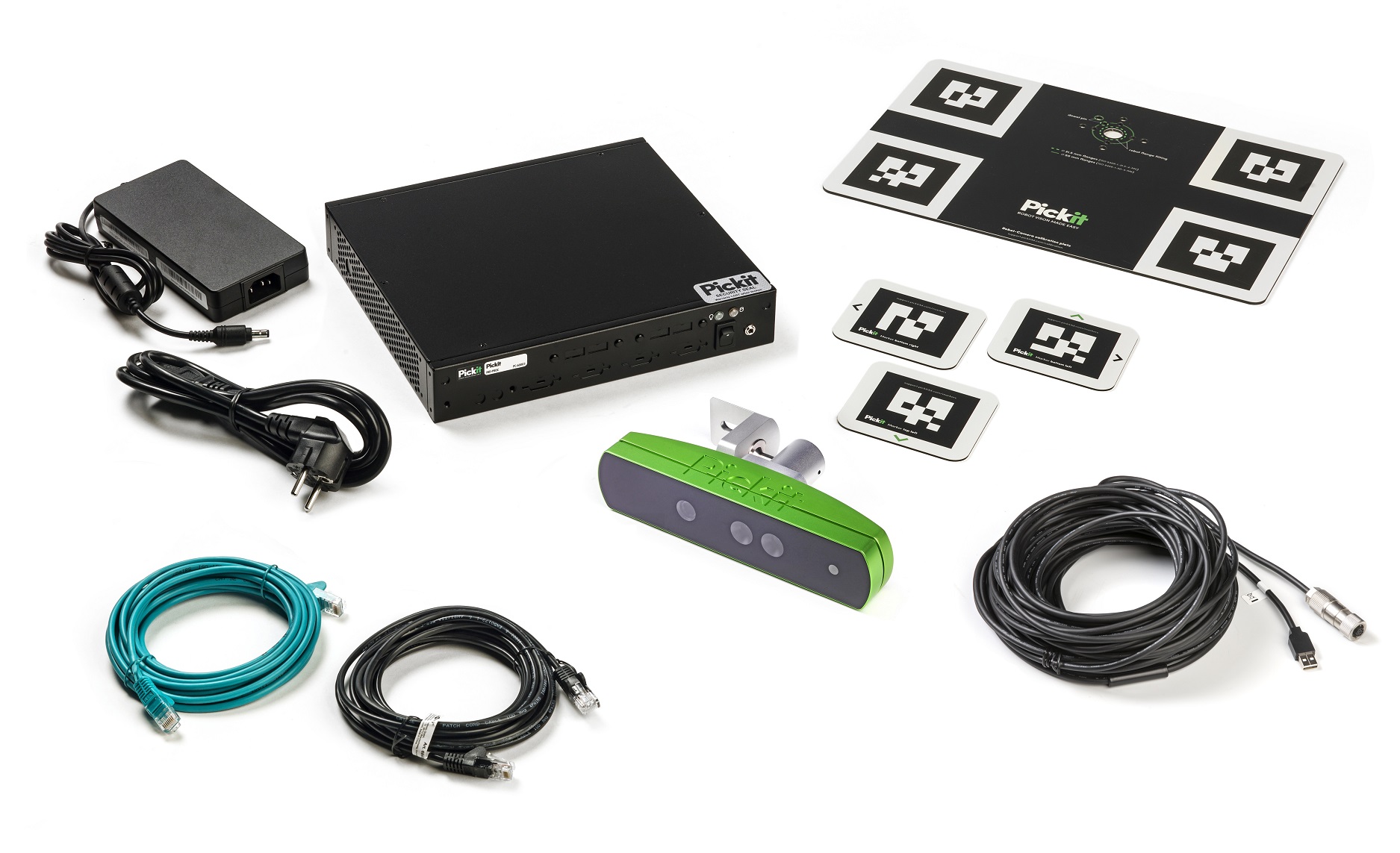
When unboxing your Pickit system, you will find the following components inside:
Pickit processor with power supply and rack/wall mounting kit.
Robot-camera calibration plates (one or more).
Region Of Interest (ROI) markers (set of three).
Two 5m Ethernet cables (CAT 6) for connecting to a robot and to a computer for Pickit web interface access.

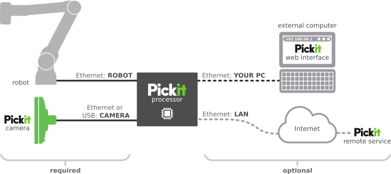
The typical way in which these components are connected together, to your robot and computer is depicted below.

The connections to the left of the Pickit processor are required to have a system running autonomously in production:
Robot: To communicate with the robot progam logic, such as exchanging object detection resquests and results.
Pickit camera: To capture images, as during an object detection request.
The connections to the right of the Pickit processor are optional, and serve the following purposes:
External computer: To access the Pickit web interface. There are two main use cases: Pickit configuration during application setup, and interactive monitoring during production.
Pickit remote service: Connection to your company network for remote Pickit service over the Internet. During normal operation, it’s not required to have this connection enabled.