Warning

You are reading the documentation for an older Pickit release (3.2). Documentation for the latest release (3.3) can be found here.

Tool Center Point accuracy

What is the Tool Center Point (TCP) ?

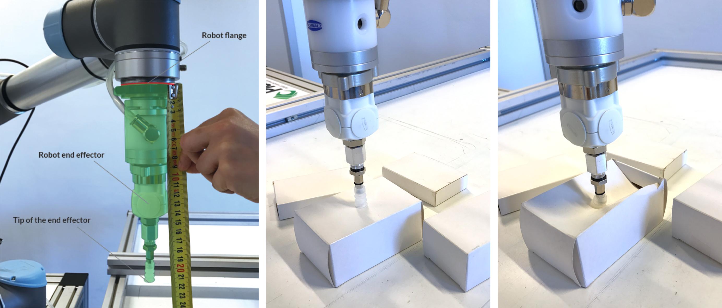
In a picking application, the robot is normally equipped with a grasping tool, like a suction cup, a magnet, a two-finger gripper, or some other type of tool. This can be seen as en extension to the robot flange, and can have any shape. In order to move to a correct position from which the tool can grasp the object, the robot program needs to know the position of the tip of the tool relative to the robot flange. This transform is commonly known as the Tool Center Point (TCP).

If you observe inaccurate picks in your application, this can be due to several reasons, one of them being an inaccurate TCP definition.

Tip

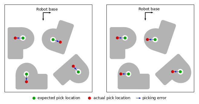
Errors on the TCP always manifest in the same manner with respect to the object, as illustrated in the figure below, left. If, instead, you observe that the error is constant relatively to the robot base (right), then the robot-camera calibration error is probably the cause.

../../../_images/tcp_vs_rc_error.png

Note

TCP errors do not appear in manually taught waypoints. A blind application using only fixed waypoints might therefore work even with an innacurate TCP. But any application using vision will need an accurate TCP.

Verifying the TCP accuracy

Note

Sometimes, a bad picking accuracy can be due to a loose tool mount. Mechanical play can make the tool move slightly, under the effect of gravity and robot motions. Make sure to rigidly mount your tool before verifying your TCP.

Find a pointy object, such as a nail, and place it at reach of the robot, pointing up. Jog the robot such that the tip of the tool is centered with the tip of the pointy object.

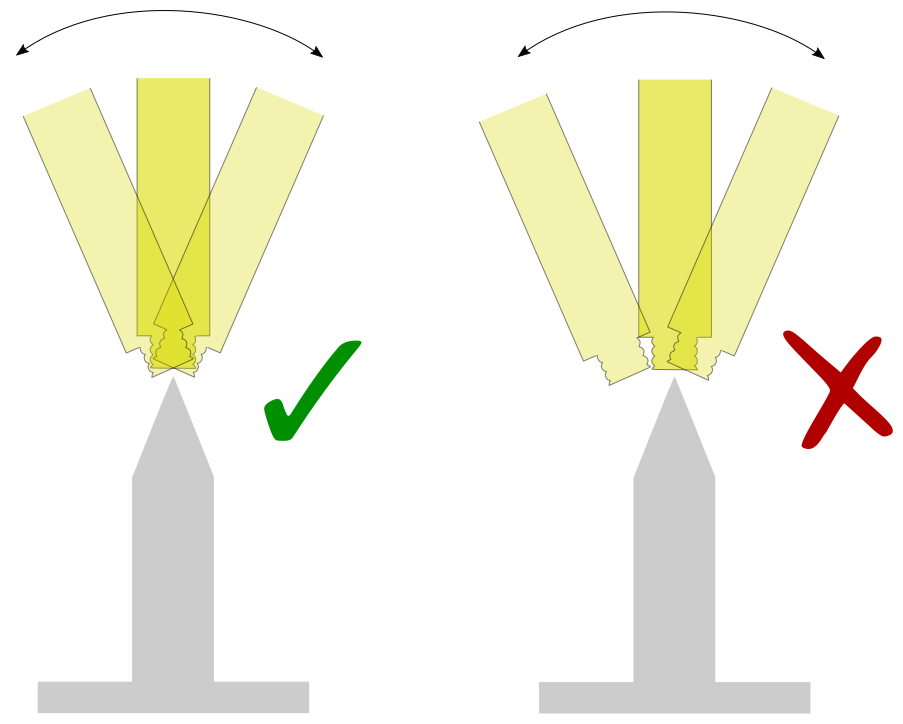
Rotate the robot around the tool frame axis pointing away from the flange. This typically corresponds to the tool Z axis. The tip of the tool should remain centered with the pointy object, and not drift visibly in any direction.

../../../_images/tcp_check_z.png

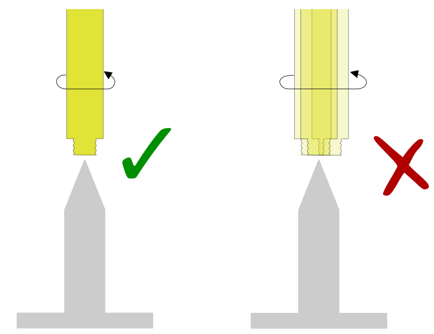
The following videos show this test with an inaccurate (left) and accurate TCP (right):

Repeat, this time rotating around the other two tool frame axes. For instance, first around X and then around Y. Also here, the TCP should not move with respect to the nail.

../../../_images/tcp_check_xy.png

Tip

To make sure you are rotating around the tool frame and not the robot frame, you can perform the above rotations with the tool tilted with respect to the vertical.

../../../_images/tilted_tool.jpg

Compliance in the approach direction

It is often desirable for tools to have a compliant element along the pick approach direction, typical examples being suction cup bellows or springs. This element compresses to a certain extent when picking, and after retreating it goes back to its original uncompressed state.

Having such compliance helps to produce a firmer grasp, absorbs picking errors in the approach direction, and can help to prevent robot stops when unforeseen tool collisions take place.

../../../_images/tool_z_compliance.png

In the example below, the offset between the flange and the fully-extended suction cup bellows is 220 mm (below left), and the bellows can compress up to 20 mm. The TCP offset is set to to 210 mm (below center) which allows it to compensate a ±10 mm error in the approach direction. If the TCP offset is set too short, beyond what the bellows can compress, we risk damaging the parts or the robot (below right). If, on the other hand, we set the TCP offset too large (greater than 220mm), the tool will not contact the part and fail to pick it (not pictured).

../../../_images/tcp_z_offset.jpeg

Correcting the TCP

If visible deviations are observed in any of the tests above, the TCP transform needs to be corrected. Most robot brands provide convenient ways to teach the TCP very precisely. If this is not the case of your robot, you need to fine-tune the TCP transform manually, until the tests above show no visible deviations.

Tip

The directions in which the correction should be applied are not always obvious. To efficiently find out, change one direction at a time and observe the impact after each change. It may help to initially apply a large correction (ex. 20 mm), that clearly indicates the affected direction.