Warning
You are reading the documentation for an older Pickit release (3.4). Documentation for the latest release (4.0) can be found here.
How does the Pickit 3D camera work?
The Pickit 3D cameras use different technologies for capturing 3D point clouds: structured light, laser triangulation, and active stereo vision.
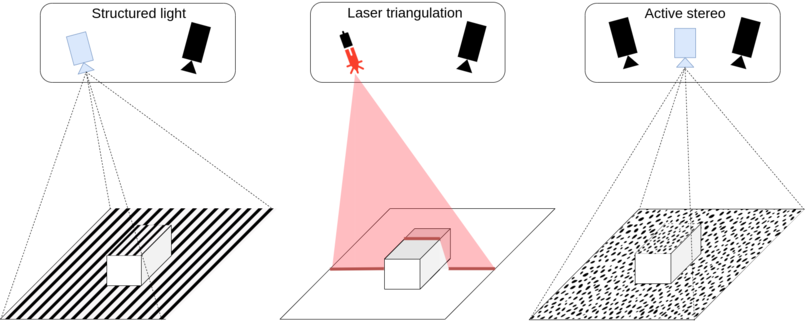
Structured light projects a known pattern onto the scene, and the camera detects the deformations of this pattern to determine the distances of points on the illuminated surface. Laser triangulation achieves similar results by projecting a laser line and sweeping it through the scene to capture its deformation. Active stereo vision, on the other hand, uses two cameras along with a projector that creates a (pseudo) random pattern. It examines the differences between the captured images and reconstructs the 3D geometry based on this analysis.
The image below illustrates the structured light principle. The red triangle represents the projected pattern, while the green triangle represents where the sensor can detect it. When there is an overlap between the two, 3D data in the form of a point cloud can be obtained, shown as a thick green line. In this case, there is 3D data for the upper part of the circle and for the flat surface below it.
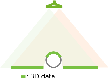
The concept is also valid for the other types of camera, with the projected pattern being replaced by the laser or the field of view of the second camera in stereo vision.
What surface of the object gets detected by the camera?
From the image above you can see that the camera can’t obtain 3D data for the full circle. Only the visible upper part is detected. Both the object shape and location (position and orientation) with respect to the camera determine which surfaces will be detected by the camera. In this section, two different examples are discussed.
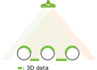
In the image below three circles are placed under the camera. Here it is shown that the obtained 3D data depends on where objects are located with respect to the camera. The detected surfaces are those that have a direct line of sight to both the sensor (green triangle) and the second source (red triangle), which can be either a projector or a second camera in the case of stereo vision.
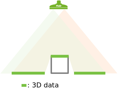
An interesting situation arises when a rectangular shape gets placed directly beneath the camera, as in the image below. In such a case, only the upper side of the rectangle is detected. There is no 3D information for the standing sides as they are not visible to the camera.
What are the limits of the Pickit cameras?
There are limits to what the Pickit cameras can detect. In this section, three different scenarios where 3D data from an object cannot be extracted from the scene are explained.
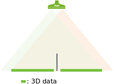
The first scenario is a special case of the rectangle discussed in the previous section of this article. Below, the effect of a thin standing edge is shown. The edge itself is rather thin so no 3D data can be obtained on top of it. Also, 3D data on the flat surface around the edge is missing where there is only visibility to either the sensor (green triangle) or the second source (red triangle), but not both: The region next to the left side of the edge is visible to the sensor but not to the second source. Conversely, the region next to the right side of the edge is visible to the second source but not to the sensor.
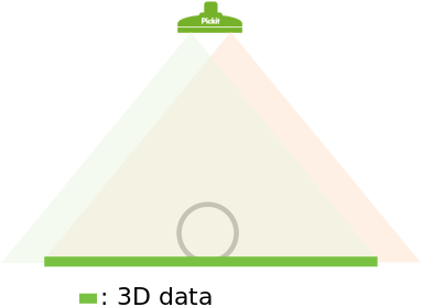
The second scenario consists of a transparent object. In the image below it can be seen that both the sensor and the second source pass through the object. So 3D data of the flat surface below the object is returned, but no information of the object itself is obtained.
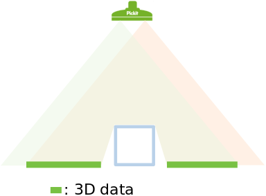
A third scenario is when the object is reflective. In this case, the pattern projected by the camera (visible light, infrared, or laser stripe) will be reflected away from the sensor. This reflection prevents the camera from capturing 3D information around the object, as shown in the image below.
The above scenarios exemplify edge cases. Often parts are only partially reflective or semi-transparent. When in doubt about a part, it is recommended to test it by placing it under the camera, trigger a detection and inspect the point cloud in the Points view. If not enough 3D data is captured, adjusting the settings might improve the quality of the results. If still not enough 3D is obtained the parts are too reflective or too transparent.