Warning
You are reading the documentation for an older Pickit release (3.4). Documentation for the latest release (4.0) can be found here.
Explaining the Teach detection parameters
The Pickit Teach detection engine is designed to detect complex 3D shapes. This article explains its detection parameters.
Camera settings
Depending on which Pickit camera is being used, different camera settings can be displayed to optimize the image capture for the current scene.
The SD2 camera allows fusing multiple captures to improve detail in regions that show flickering in the live stream. Enabling the advanced settings for this camera exposes settings like the strength of the projected infrared pattern for finer control of over/under exposure.
The M-HD2 and L-HD2 cameras allow choosing between pre-configured presets, including highly configurable advanced settings.
The XL-HD2 camera allows setting the compromise between capture speed and quality, as well as filters for improving the quality of the results.
Define models
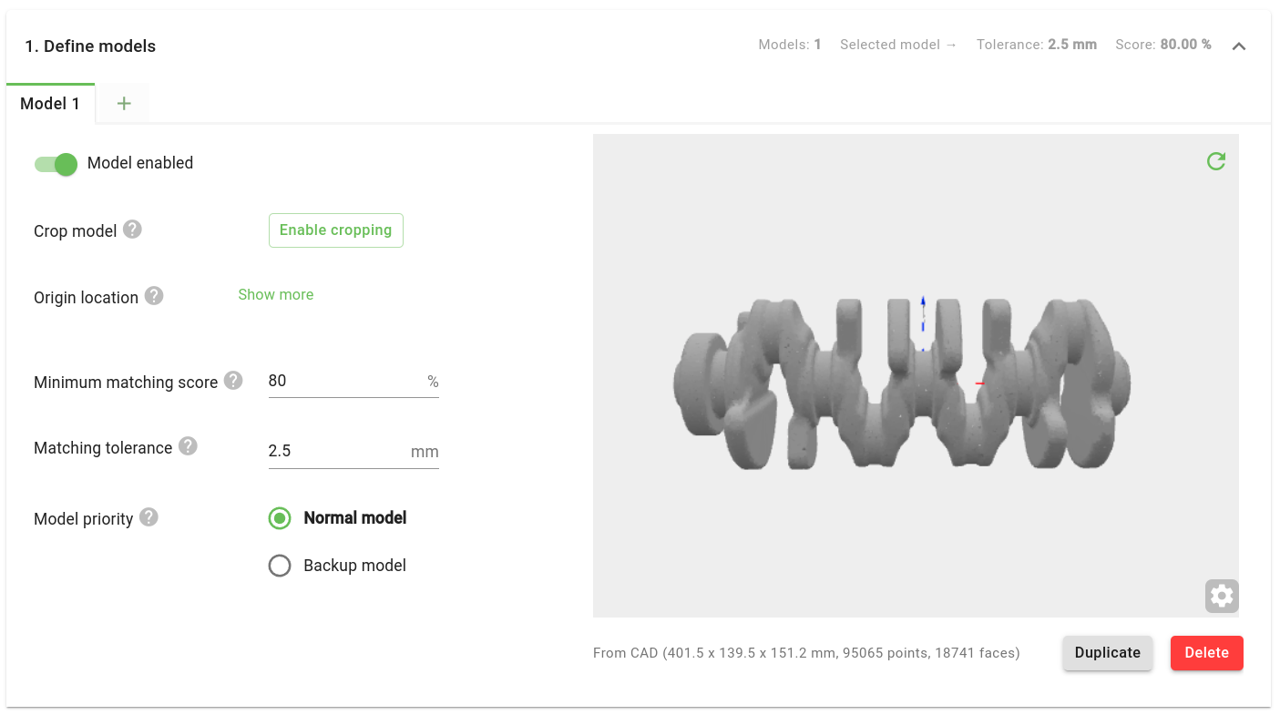
A list of taught models is shown accompanied by their ID and the number of points. By default, there are no models defined.
Add a model
Press Teach from camera or Teach from CAD to teach your first model. The points currently visible within the ROI are now saved into a model. When the model is successfully created, the model will automatically be shown in the tab.
To add extra models, press + in the model tab. In one product file, up to eight different models can be taught. This means that Pickit Teach is capable of looking for 8 different shapes in one detection. The model ID of a detected part can be queried from the robot program and is part of the information that can be used to implement smart placing strategies.
Re-teach a model
A model taught from the camera can be retaught by pressing Re-teach. By pressing this button, the points currently visible within the ROI are saved into the model.
Warning
When re-teaching a specific model, the point-cloud data from the previous model is overwritten. This action cannot be undone.
It is also possible to crop or expand an existing model, without the need to re-teach it. Refer to the article How to edit an existing Pickit Teach model for further details.
Delete a model
To delete a model, press Delete for the specific model.
Warning
Model ID’s will be reassigned after deleting a model. If you use model ID’s in your robot program, make sure they’re up to date after deleting models.
Warning
Model data will be lost after deletion and cannot be restored.
Select and visualize a model
A model can be selected by clicking on the respective tab. The open model can then be visualized in a specific window inside the tab.
Enable or disable a model
A model is enabled by default, and can be disabled through the toggle switch at the left of the respective tab. If a model is disabled, it will be ignored in subsequent detection runs. Disabling models is a quick and useful way to check the effect of different combinations of models, or to test distinct models in isolation (by disabling all others).
Edit origin location
The location of the model origin can be edited either by setting exact values, or interactively via Enable drag handles in 3D viewer.
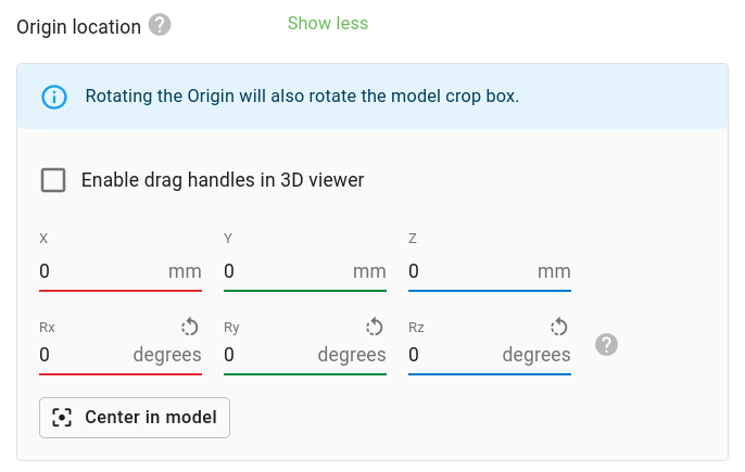
This can be useful for:
Setting a meaningful model crop box orientation, especially when teaching from camera.
Having an intuitive frame from which to specify pick point locations.
Having an intuitive frame for specifying the expected object location.
Crop model
For camera and primitive shape models, the model can be cropped via the Enable cropping button. Learn more about this feature here.
Matching tolerance
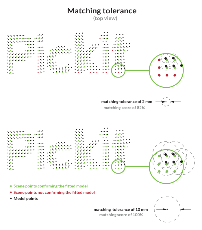
If the distance between a detected scene point and a point of your model is below this position tolerance value, then this scene point will confirm the model point. This parameter has a big impact on the scoring of the Minimum matching score.
Learn more about finding a good value for this parameter here.
Minimum matching score
Minimum percentage of model points that need to be confirmed by scene points, for the detected object to be considered valid.
Note
For CAD models, only the points that could be visible from the camera are used in the computation of the matching score.
Learn more about finding a good value for this parameter here.
Model priority
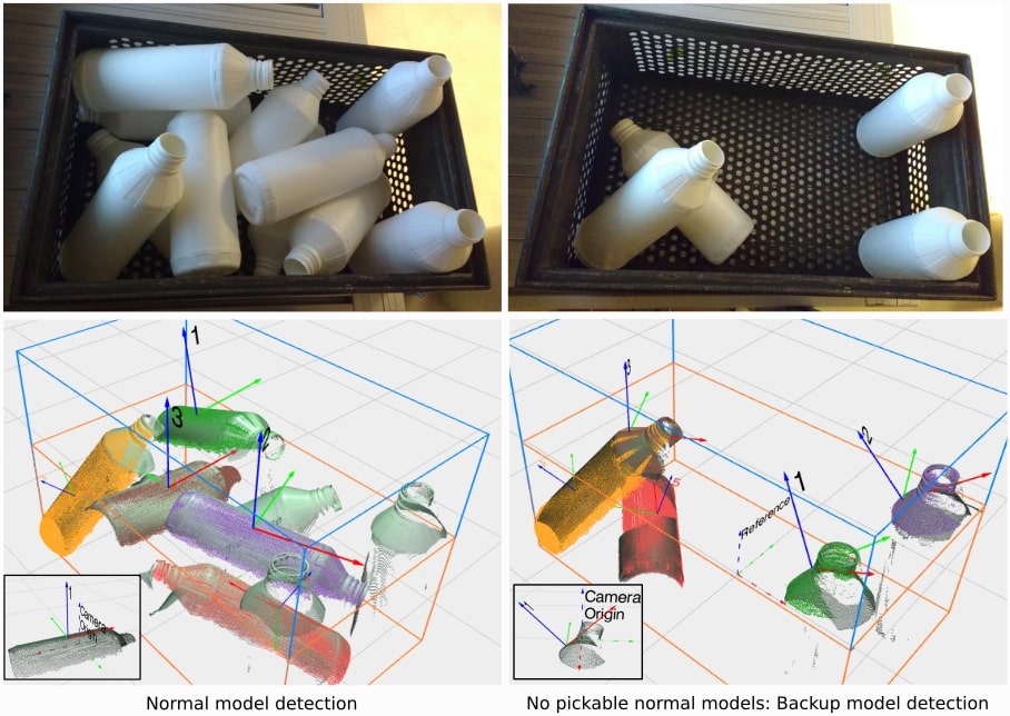
In some applications, it is desired that certain models have preference over others. For such cases, Pickit allows setting different priority levels to models. A model can be normal (high priority) or backup (low priority). Backup models are only searched for if no normal model is pickable.
For instance, let’s consider that we are picking white bottles from a bin. The bottles can be either lying down (most common case) or standing up. Let’s suppose that it is easier and faster to pick and place the bottles lying down (less robot motions, firmer grasp). By setting the standing bottle model priority to backup, such bottles are only looked for when there are no pickable or detectable bottles lying down.
Note
Notice that the above example consists of multiple models captured using teach from camera. If you instead have a CAD model of the white bottle, the complete part shape is contained in a single model. In this case, you can prioritize the bottle pick location by using pick point priorities.
Filter objects
These parameters specify filters for rejecting detected objects. Rejected objects are shown in the Objects table as invalid.
Expected object location
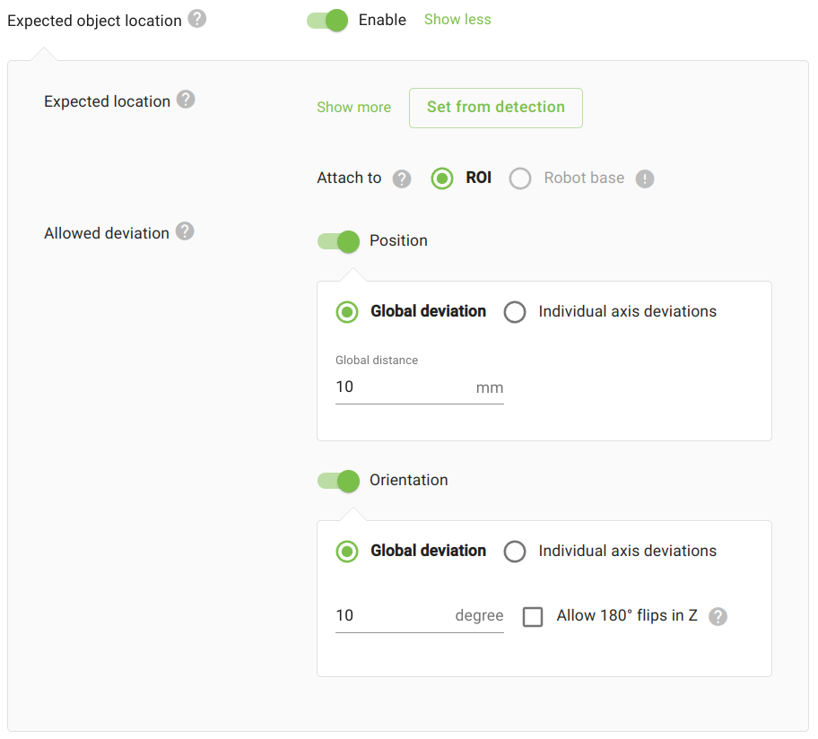
In applications like surface treatment (sanding, deburring) or dispensing (gluing, sealing), the location of the part to process is roughly known in advance, and object detection is used to pinpoint its exact location. In such applications, it is often desired to reject parts that deviate too much from an expected location (learn more).

To use this filter, you need to specify:
The expected location of the object
Origin(not its pick point). This can be done by taking the location of an existing detection (recommended), by interactively using the 3D drag handles, or by manually setting the values.The allowed deviation of a detected object from its expected location. It can be specified as a global position and/or orientation value, or on individual axes
For example, in the de-racking application shown below we expect car doors to not deviate too much from an expected position in the X and Y directions, but we want to leave the Z (rack) direction unconstrained. For orientation, it’s sufficient to specify a single global deviation.
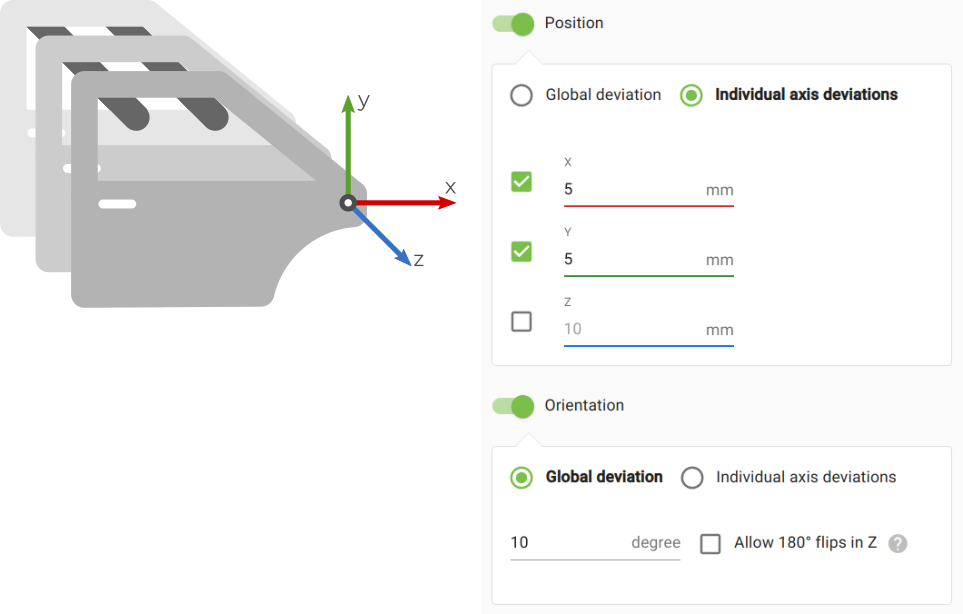
Furthermore, in such applications it can be useful to communicate to the robot the relative offset from the expected location instead of an absolute location with respect to the robot base. This can be done by editing the object reference frame.
Optimize detections
Flat objects
This feature allows to detect objects based on their edges. It is especially useful for flat objects, like sheet metal plates. When enabled, an additional input to specify the object thickness is needed.
Models of flat parts can be taught from camera or from a 2D CAD model.
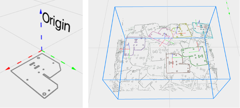
Image fusion (SD cameras only)
Image fusion is the combination of multiple camera captures into a single image. Enabling image fusion can provide more detail in regions that show flickering in the 2D or 3D live streams. Flickering typically occurs when working with reflective materials. There are three possible fusion configurations: None, Light fusion and Heavy fusion.
Image fusion can increase total detection time by up to a second. The recommended practice is to use None in the absence of flickering, and try first Light fusion over Heavy fusion when flickering is present.
Downsampling resolution
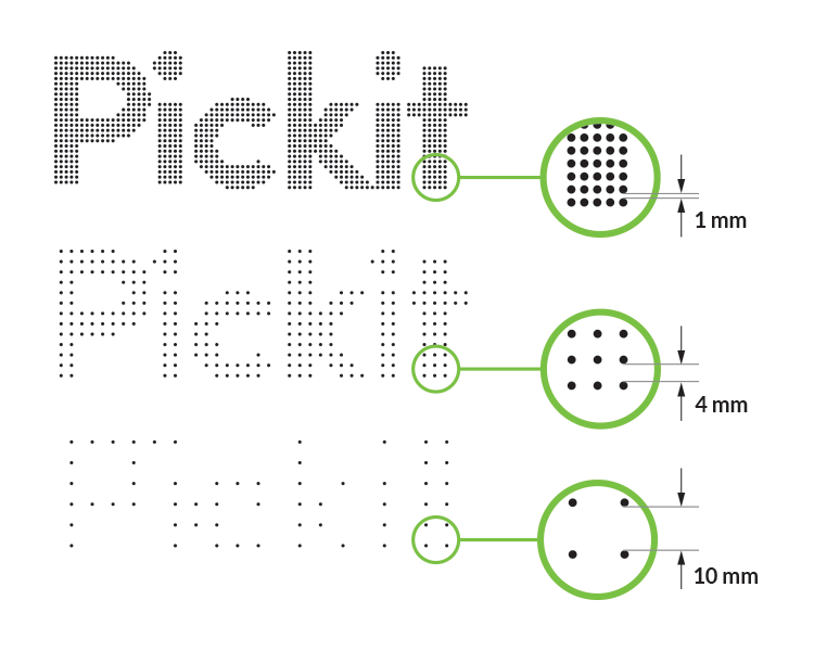
The downsampling resolution allows reducing the density of the point cloud. This parameter has a big impact on detection time, and to a lesser extent on detection accuracy. More points lead to higher detection times and higher accuracy, fewer points to lower detection times and lower accuracy.
In the illustration, you can see an example of setting the scene downsampling parameter to 1 mm, 4 mm and 10 mm.
Detection speed
With this parameter, you can specify how hard Pickit Teach tries to find multiple matches. Slower detection speeds are likely to produce more matches. There are three available options:
Fast Recommended for simple scenes with a single or few objects.
Normal This is the default choice and represents a good compromise between a number of matches and detection speed.
Slow Recommended for scenes with many parts, potentially overlapping and in clutter.
Example: Two-step bin picking.
Pick an individual part from a bin using Normal or Slow detection speed and place it on a flat surface.
Perform an orientation check for re-grasping using Fast detection speed, as the part is isolated. Grasp and place in final location.