Warning
You are reading the documentation for an older Pickit release (2.0). Documentation for the latest release (4.0) can be found here.
How to use Pickit Flex
The Pickit Flex detection engine has a typical workflow, which is described step by step in this article.
Define the 3D scene
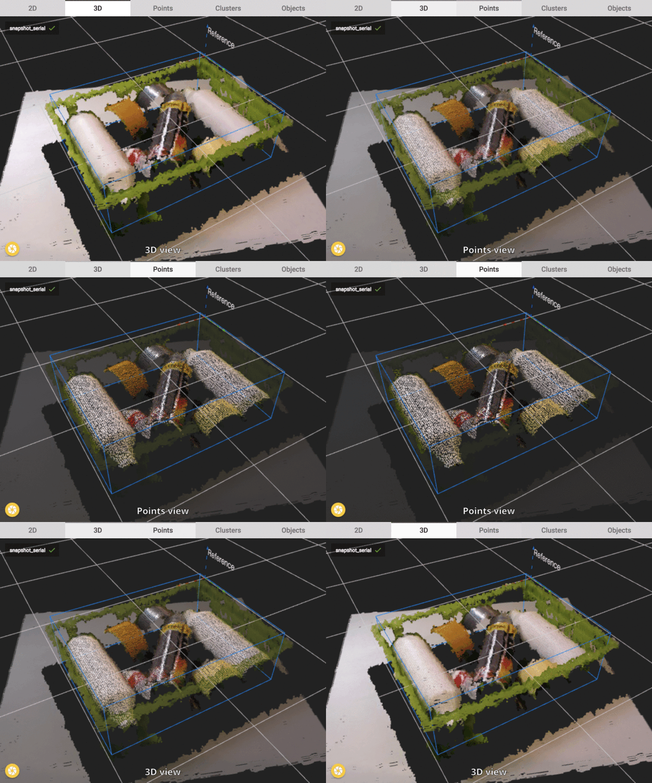
The first step of Pickit Flex is to define where the Pickit system should look. The 3D scene is defined by a Region of Interest and the optimize detection parameters. These detection parameters are explained in the article Explaining the Flex detection parameters.
In the image below an example of a good defined scene is shown. First, in the 3D view all points within the field of view of the camera are shown. Second, in the Points view only the points of the parts in the bin are shown. The table and the bin are filtered out. Also it can be seen that the space in between points have gotten bigger in the second view.
The information shown in the Points view is what will be transferred to the next step. All other information is not taken into account for the detection with Pickit Flex.

Divide the scene into clusters & reject (some) clusters
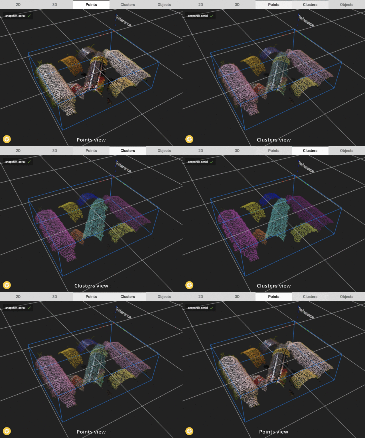
The next step in the Pickit Flex detection is rather important. Here the scene will be divided into different parts(clusters). Each cluster contains all points that belong to one object in the scene. All clusters are shown in a different color.
In the image below the effect of clustering is visualized. The 3D scene is now divided into 7 different clusters(all shown in a different color). Also it can be noted that the Clusters view contains less points than the Points view. This is due to the user defined settings that certain clusters are rejected. In this case smaller clusters are rejected(not visualized in the image below). It makes sense to reject smaller clusters because they often represent noise or partially covered objects. So these points are then excluded from the following step.
For the Flex detection to work properly every object should be clustered apart. A bad example would be one cluster(color) for 2 parts in the scene. The Pickit system supports different ways of clustering. All methods are explained in the Explaining the Flex detection parameters.

Fit & filter objects
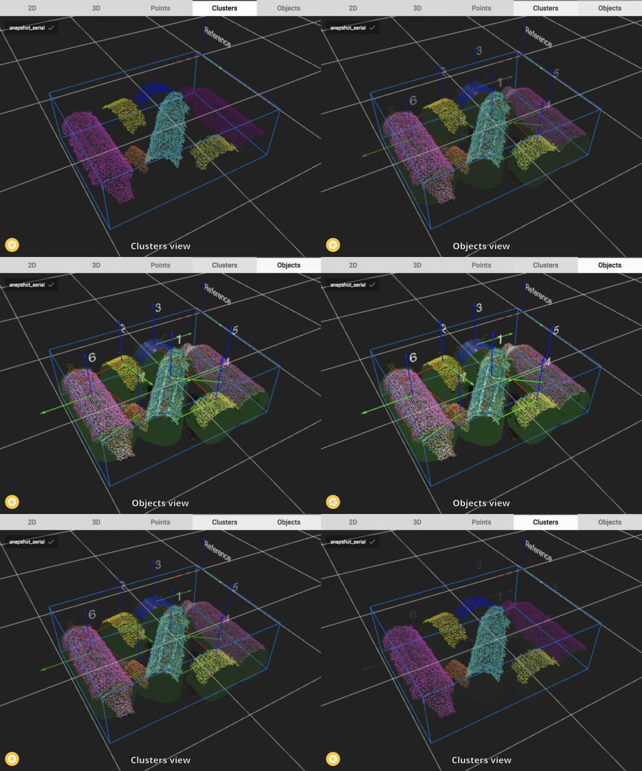
The final step of Pickit flex is to fit a certain geometric shape on every cluster and to filter out the wrong objects. All accepted objects can be send back to the robot one by one.
For each cluster that was accepted in the previous step now a shape is fitted. In the image below we see that each cluster gives rise to a object. Seven green cylinders and all points in the Region of Interest are shown in the Objects view.
In this last step it is decided which objects are accepted as good fits. These good fits can then be sent back to the robot. Filtering of the objects is done on their parameters shown in the Detection grid. An explanation of all these parameters can be found in the article Explaining the Flex detection parameters.
