Warning
You are reading the documentation for an older Pickit release (2.1). Documentation for the latest release (4.1) can be found here.
Setting up Pickit with a Fanuc robot
This setup manual helps you setup Pickit with a Fanuc robot. The setup of Pickit with a Fanuc robot consists of 4 steps:
Check controller and software compatibility
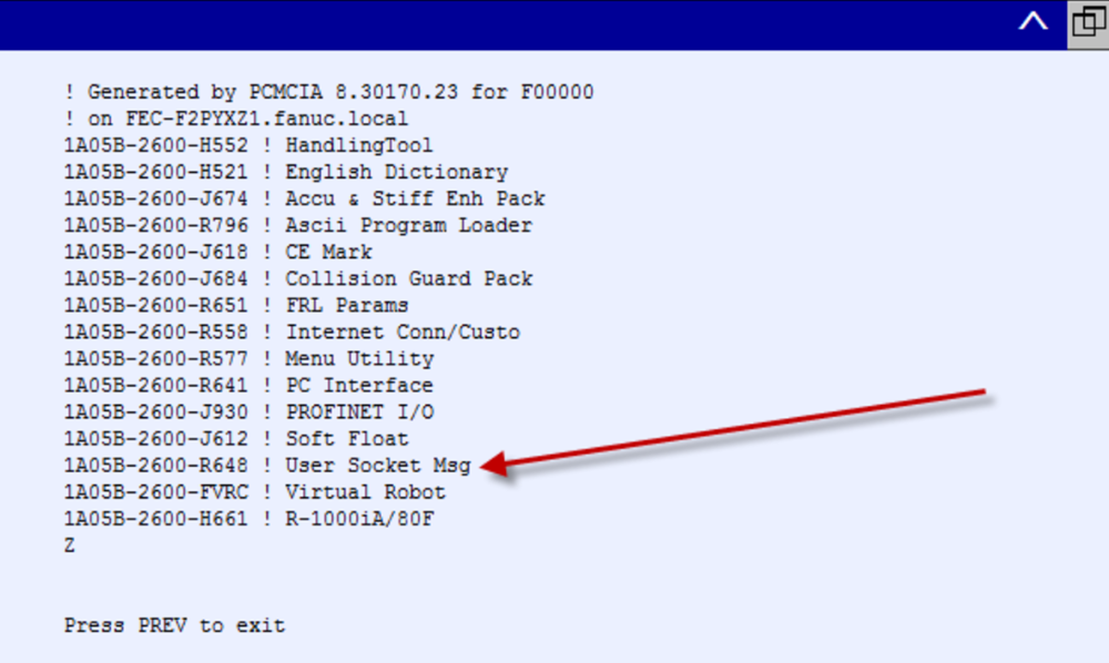
Pickit is compatible with controllers as of version R-J3iB and the software module User Socket Msg for socket communication is required. (The product number for this module is A05B-2600-R648).
To verify if that software module is installed open the Status version ID page by opening MENU > STATUS > Version ID and then click the ORDER FI button.
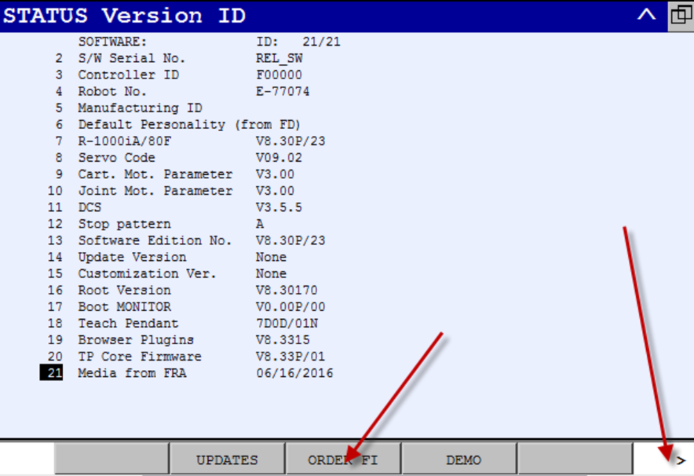
Here you can check now if the module is listed as shown below. Note that also the software version (V8.30P in the above example) can be verified here.
Alternatively, a backup of the controller can be made and the
information on the installed software can be found in the following
file: ~/backup/All Of Above/orderfil.dat.
To get you started as quickly as possible, Pickit provides:
All ASCII files for both the low-level communication as well as an example program.
Binaries generated from these ASCII files for software version V8.30. In case of using an older software version, you might have to recompile the ASCII files first.
Warning
Note that for the R-J3iB, the program names have to be shortened to at maximum 8 characters.
Setup the network connection
Setting up network connection for a Fanuc robot consists of 3 steps:
Hardware connection
The Pickit processor has to be connected to the Fanuc controller using an Ethernet cable. This Ethernet cable should be plugged in:
The ROBOT port of the Pickit processor;
The Port 1 port of Fanuc controller.
The location of port 1 on the Fanuc is shown for different controller types in the images below.
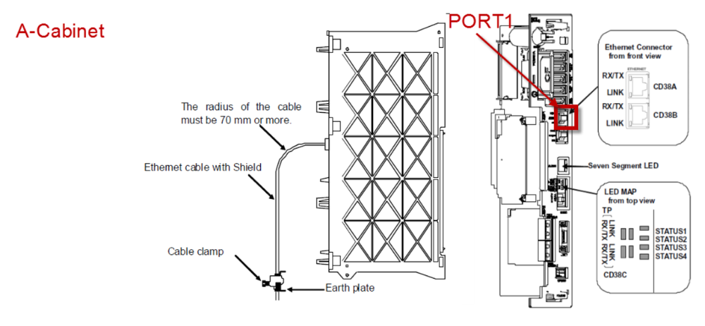
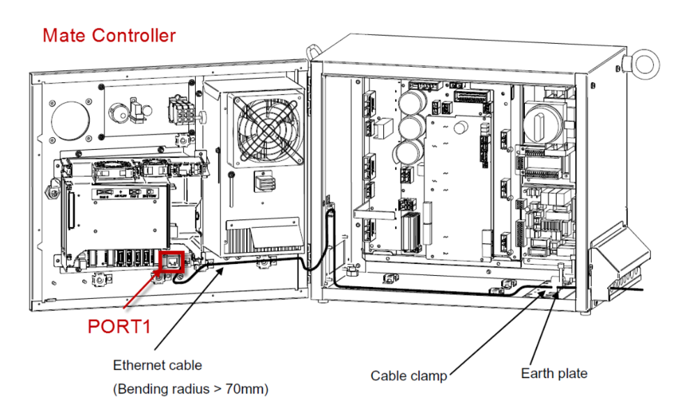
The Ethernet cable must be fastened by a cable clamp to prevent tension being applied to the RJ-45 connector, in case the Ethernet cable is pulled directly. This clamp is also used to ground the cable shield.
IP configuration
To allow communication between Pickit and the Fanuc controller both must have an IP address in the same subnet.
By default, the Pickit ROBOT connection (the Ethernet port on the Pickit processor labeled ROBOT) is configured to have the following static IP address: 169.254.5.180 with a subnet mask of 255.255.0.0.
If this setting is kept, the following has to be done at the Fanuc controller via MENU > SETUP Host Comm:
To obtain a static IP, DHCP has to be disabled on the controller.
A static IP should be set to e.g. 169.254.5.182 which is an IP in the same subnet as the Pickit IP.
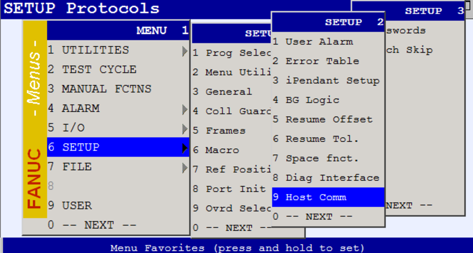
And select the TCP/IP protocol:
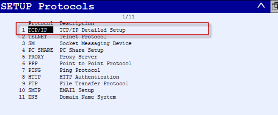
Next, you have to take the following steps:
Disable DHCP by pressing the DHCP
Set the correct IP address and subnet mask for Port#1
Activate these new settings via NEXT > INIT
To verify now if a network connection can be made between Pickit and the robot controller, you can create a new host name ‘pickit’ and give it the Pickit ROBOT connection IP address. After pressing the PING button, you should see the following message printed:
Ping 169.254.5.180 succeeded
Socket configuration
Pickit works through socket communication. To work properly Pickit has to act as the server for the socket communication. Hence, the robot controller has to be configured to be client.
To do so, select Clients after pressing SHOW in the same SETUP protocols menu used above.
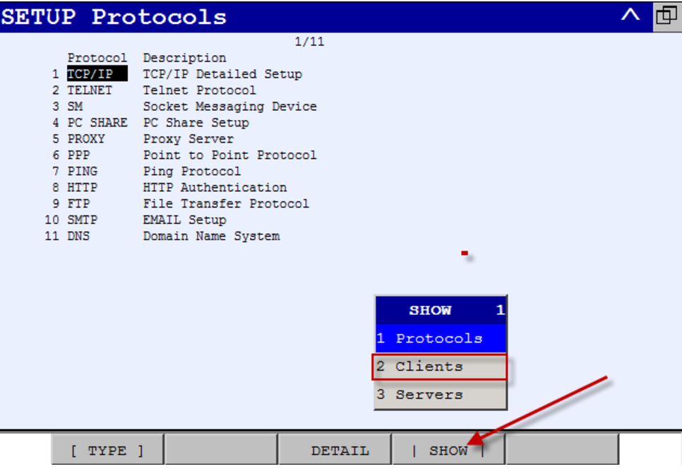
Next, select DETAIL to configure the client C1 as follows:
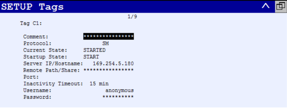
To set the Startup State to START you have to use the [[CHOICE]] button.
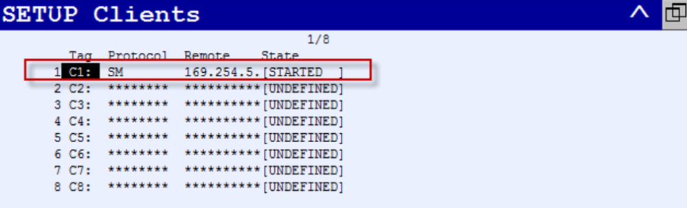
To verify if the configuration of the socket is done correctly, you have to reboot the controller and go again to MENU > SETUP > Host comm and then pressing SHOW and CLIENTS. You should see the following:
Load the program files
Loading the program files for a Fanuc robot consists of:
Additionally we provide some extra insights on registers used by the Karel program.
Download the right files
Download the Pickit Fanuc files
The .zip folder contains the following ASCII files:
pick_it_communication13_C.klis a Karel program that cares of the low level communication. This files should not be adapted.EXAMPLE_PICK_IT.LSis a Teach Pendant program that shows a simple pick application for FANUC using Pickit.For calibration we provide two Teach Pendant programs;
MP_CALIBRATE.LSfor Multi poses calibrationCALIBRATE.LSfor Single pose calibration
The other
*.LSfile define short Teach Pendant program that abstract some of the Pickit logic into more user readable functions. They can also serve as macros that can be called manually. More about that later.
Tip
In case of using Fanuc software version v8.30, you can directly use the binaries available in the downloaded folder. In the other case, you first have to compile the above files into binaries.
Warning
Modifying the pick_it_communication13_C.kl file should only be considered after talking to a Pickit support engineer.
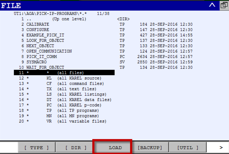
Upload the files to the robot
Uploading the files can be done using an FTP server or by manually loading them on the robot using a USB stick mounted to the Teach Pendant. For the latter, you have to go to MENU > FILE > UTIL > Set Device > Select your device.
Warning
The available binary files contain a configuration file for defining macros: SYSMACRO.SV.
When this file is uploaded it automatically removes all existing macros and replaces them with the Pickit macros.
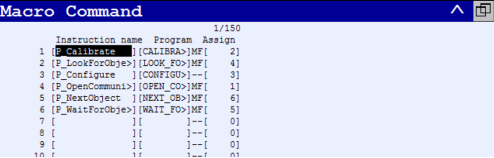
To prevent the removal of the existing macros, don’t upload SYSMACRO.SV, but configure the new macros manually in MENU > SETUP > Macro.
In case all binaries are loaded correctly, you can check if the macros are available via MENU > SETUP > Macro.
Registers used by the Karel program
The Karel program pick_it_communication13_C.kl, which takes care of the low-level communication between the controller and Pickit, uses the following IO and registers to pass on data from the low-level communication to a Teach Pendant application program:
Data communicated from Pickit via the Karel program to the Teach Pendant application program:
PR[1]: pose of an object detected by Pickit.
R[2]: the Pickit status.
R[6]: Pickit object dimension x.
R[7]: Pickit object dimension y.
R[8]: Pickit object dimension z.
Data communicated from the Teach Pendant application program via the Karel program to Pickit:
R[1]: the command for Pickit.
R[4]: the desired setup.
R[5]: the desired product.
Additional pose registers used in the EXAMPLE_PICK_IT program:
PR[2]: the current configuration of the robot. This configuration is calculated by calling SET_PICK_POSE.
PR[3]: the final pose where the robot will pick the part.
Tip
If these registers are already used on your robot. Please contact us at support@pickit3d.com and we will assist you in finding a solution.
Tip
To make the Karel programs visible on the Teach Pendant, you have to set the KAREL_ENB value to 1 via MENU > NEXT > SYSTEM > SYSVARS.
Start and verify communication
Starting and verifying communication for a Fanuc robot consists of 2 steps:
Start communication
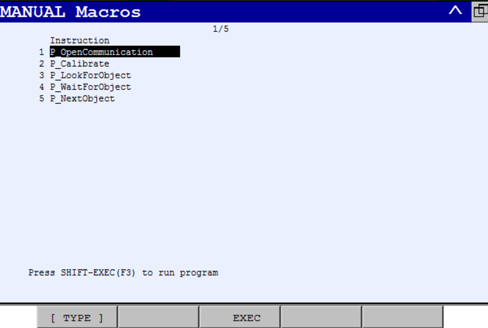
To start the communication manually, on the robot you have to go to MENU > MANUAL FCTNS, select P_OpenCommunication and press SHIFT+EXEC.
Verify communication
Verify on the robot:
In case the communication was started successfully, you can see the following on the robot Teach Pendant:
C1_CONNECTED is shown in the top status barVerify on the Pickit interface

You can verify the connection from within the Pickit web interface by checking if there is a checkmark next to the robot status label in the top bar.
Test robot connection on Pickit
Details on testing this connection can be found on: Testing the Robot to Pickit connection