Warning
You are reading the documentation for an older Pickit release (2.1). Documentation for the latest release (4.1) can be found here.
Setting up Pickit with a KUKA robot
The setup of Pickit with an KUKA robot consists of 4 steps:
Check controller and software compatibility
Pickit is compatible with controllers as of version KR-C4 and the software module KUKA Connect KRC for socket communication is required. The product number for this module is 91B300-020 version 2.0.14 or later.
Tip
This module can only be purchased through Pickit. Please contact your account manager or sales@pickit3d.com for more information.
Verify if already installed
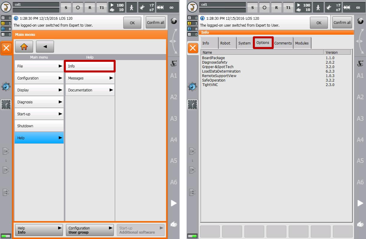
To verify whether the KUKA Connect KRC module is already installedon the KR-C4 controller, go to the Main Menu, then Help > Info. In the Info screen select the Options tab. The Main Menu is reachable by clicking on the round robot icon:

If an entry named Connect is listed, then the module is installed and you can skip the next subsection. If the entry is not listed, as in the image below (right), follow the remaining steps of this section to install the KUKA Connect KRC module.
Module installation
Download the Pickit KUKA files here.
The KUKA Connect KRC module can be purchased directly from KUKA, and consists of: a set of files that you should copy to a NTFS formatted USB drive, and a 16-digit license key with the format xxxx-xxxx-xxxx-xxxx that depends on the robot’s serial number.
Generation of temporary license keys by KUKA is possible for validating an application before the actual purchase of a Pickit system.
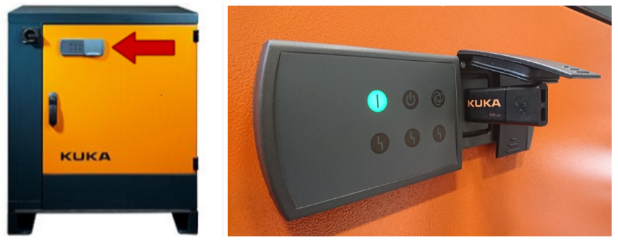
Plug in the USB drive containing the KUKA Connect KRC module files in the external USB port of the KR-C4 controller cabinet.
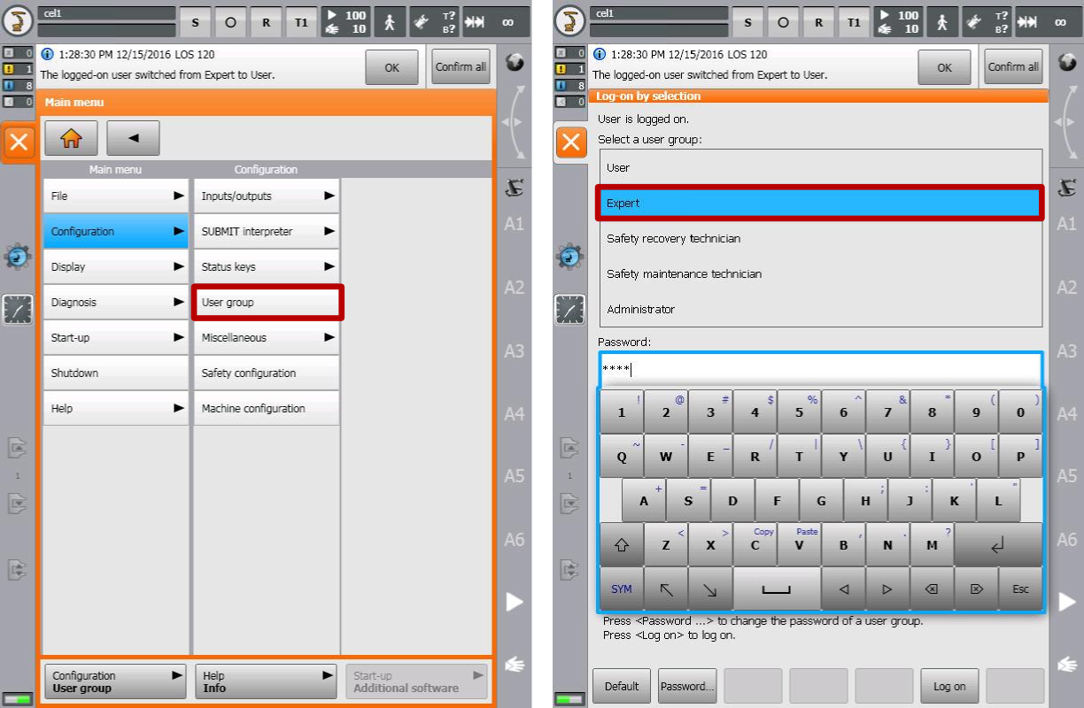
A user with expert privileges is required to install the module. To enable expert mode, go to Main Menu, then Configuration > User group and select the Expert group.
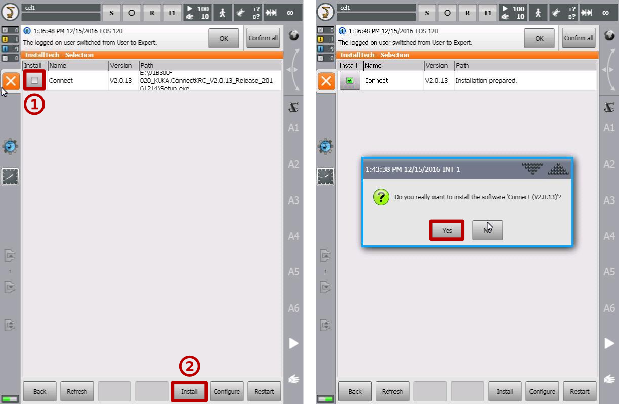
To install the module, go to Main Menu, then Start-up > Additional software. On the Additional software click the New software button at the bottom left.
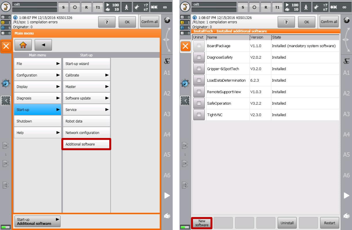
You should see a list of available modules pending for installation, including an entry named Connect. Toggle the checkbox next to the Connect module and click install. Confirm the installation on the pop-up dialog.
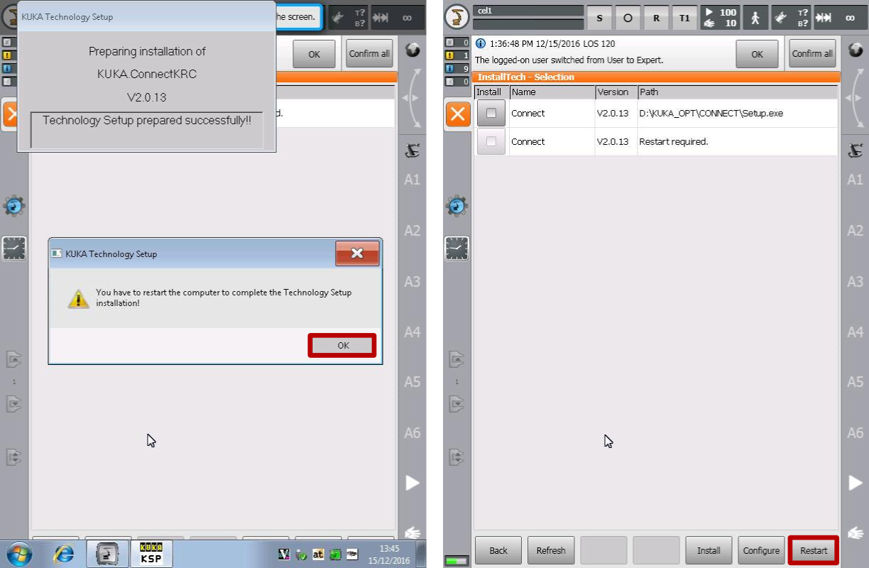
After preparing the installation, a pop-up dialog will request a controller restart to complete the installation. Dismiss the pop-up by clicking OK and click the Restart button. You can also remove the USB drive from the KR-C4 controller cabinet at this point.
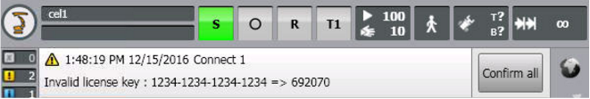
After restarting, you should see a notification at the top of the screen indicating that the Connect module has an invalid license key.
To activate the license, go to Main Menu, then Configuration > Connect settings. In the Connect settings screen click the License button.
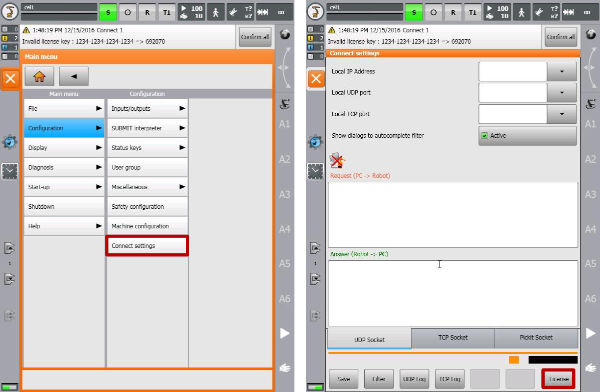
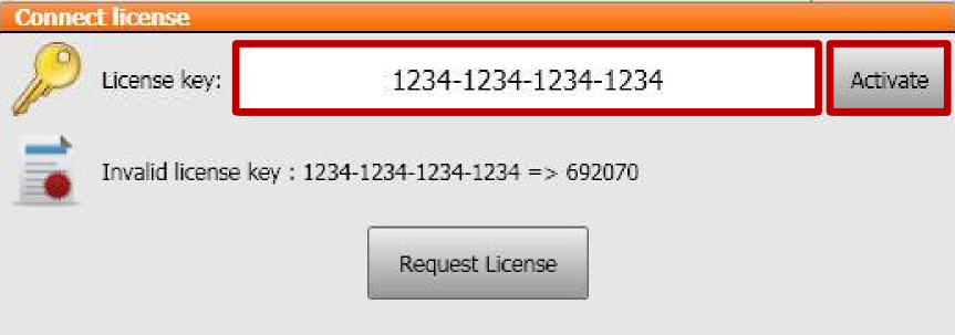
Enter the 16 digit license key associated to the robot’s serial number including dashes and click Activate.
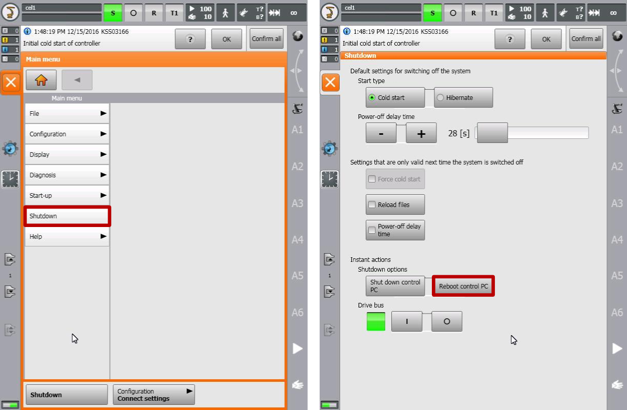
For the license key activation to take effect, another controller restart is required. To do so, go to Main Menu, then Shutdown. In the Shutdown screen click the Reboot control PC button and confirm.
SPS file settings
Apart from installing the KUKA Connect KRC module, it is necessary to add one command to the SPS file, which executes in the background of all robot programs. You need to be in expert mode to perform this operation.
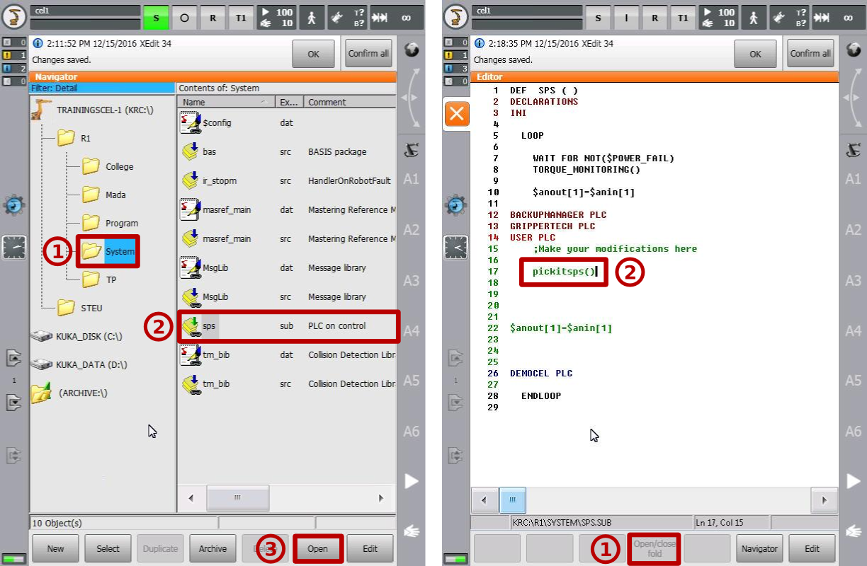
To open the SPS file from the navigator, browse to R1 > System, select the sps file and click Open, as shown in the figure below, left.
Once the file is open, move the cursor to the USER PLC line and click on Open/close fold, and add a line calling the pickitsps() function, as shown in the figure below, right. Finally, close the file to save and exit (orange close icon at left panel).
The pickitsps() function allows Pickit to have access to the robot flange pose, as opposed to the pose of the currently active tool.
KUKA KRC settings
Now that the KUKA Connect KRC module is installed, we need to configure it to communicate correctly with the Pickit system. To do this, go to Main Menu, then Configuration > Connect settings. In the Connect settings screen select the Pickit settings tab and inspect/modify the configuration, as follows, and as shown in the figure below (right):
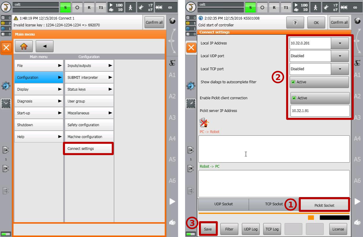
Check correctness the robot IP address. This is a read-only value shown for sanity-checking the robot configuration. If you wish to change the robot IP address, please refer to the KUKA KR-C4 user manual.
Disable the local UDP port.
Disable the local TCP port.
Activate ‘Show dialogs to autocomplete filter’.
Activate ‘Enable PickIt client connection’.
Specify the Pickit server IP address.
When communicating with KUKA robots, the Pickit server IP address cannot belong to the following IP ranges:
169.254.0.0 to 169.254.255.255
192.168.0.0 to 192.168.0.255
172.16.0.0 to 172.16.255.255
172.17.0.0 to 172.17.255.255
The default Pickit server IP is 169.254.5.180, which belongs to the first range, so it must be modified.
Click on the Save button to store the settings.
Setting up the network connection
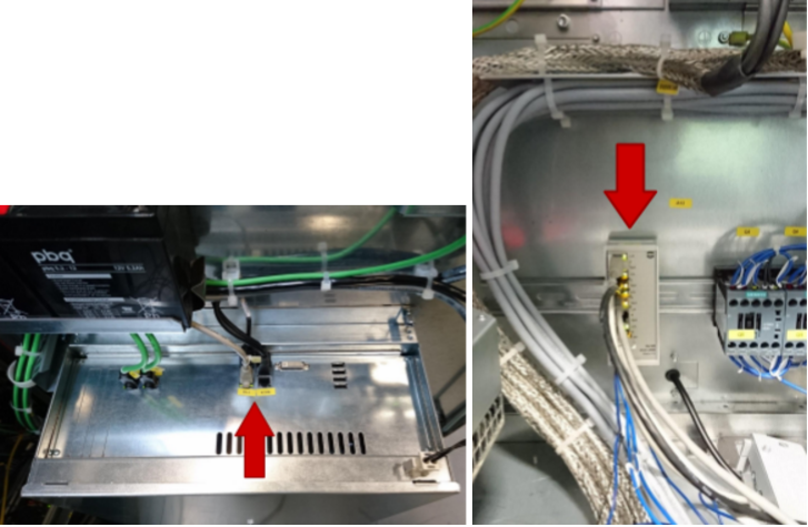
The Pickit processor has to be connected to the KUKA KR-C4 controller using an Ethernet cable. This Ethernet cable should connect:
The network port labeled ROBOT of the Pickit processor
The KLI Ethernet port of the KR-C4 controller (also referred to as X66). The location of this port may vary depending on the controller model. The below images show example locations: Cabinet door (left), built-in switch (right).
Loading the program files
There are two sets of files installed in the robot controller that relate to Pickit communication:
Pickit application files. These are example programs that illustrate how to perform typical Pickit operations, like robot-camera calibration or object detection for pick and place.These are located in R1 > Progran > Pickit.
Pickit interface files. These are internal files that expose the high-level functions used by the application files, and manage low-level communication with the Pickit system. These files are not meant for editing and are located in R1 > TP > Connect > Pickit.
The Pickit application files can be loaded and executed as any other KUKA.KRL program. Please refer to the KUKA KR-C4 user manual for further details.
The examples contained in the Pickit application files contain hard-coded robot poses that should be adapted to every new robot. When executing such programs for the first time, please do so in manual mode and at low speed to check for potential collisions.
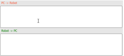
Starting and verifying the communication
Before starting the communication, on the Pickit interface select KUKA as the robot to communicate with. Next, on the robot side, go to Main Menu, then Configuration > Connect settings. In the Connect settings screen, data being exchanged between the robot and Pickit is displayed in the text boxes labeled PC -> Robot and Robot -> PC. You should see data and timestamps be updated multiple times per second.
Details on testing this connection on the Pickit side can be found on: Testing the Robot to Pickit connection.