Warning
You are reading the documentation for an older Pickit release (2.1). Documentation for the latest release (4.1) can be found here.
Setting up Pickit with a Yaskawa robot
This setup manual helps you setup Pickit with a Yaskawa robot. The setup of Pickit with a Yaskawa robot consists of 4 steps:
Check controller and software compatibility
Pickit is compatible with controllers FS100, DX200 and YRC1000 (Micro).
Note
Pickit is not yet compatible with the HC10 nor the Smart Pendant.
The parameters listed below must be declared on the controller to allow the correct operation of the application. Ask your local Yaskawa affiliate to check this.
LAN INTERFACE SETTING function set to MANUAL SETTING
MotoPlus function set to USED
MACRO INST. function set to USED
MotoPlus - Number of files set to 1 (Default setting)
MotoPlus - Number of tasks set to 5 (Default setting)
Setup the network connection
Hardware connection
The connection between the Yaskawa controller and Pickit is done over ethernet. You connect your robot controller to the ROBOT port on the Pickit processor as shown in the diagram below:
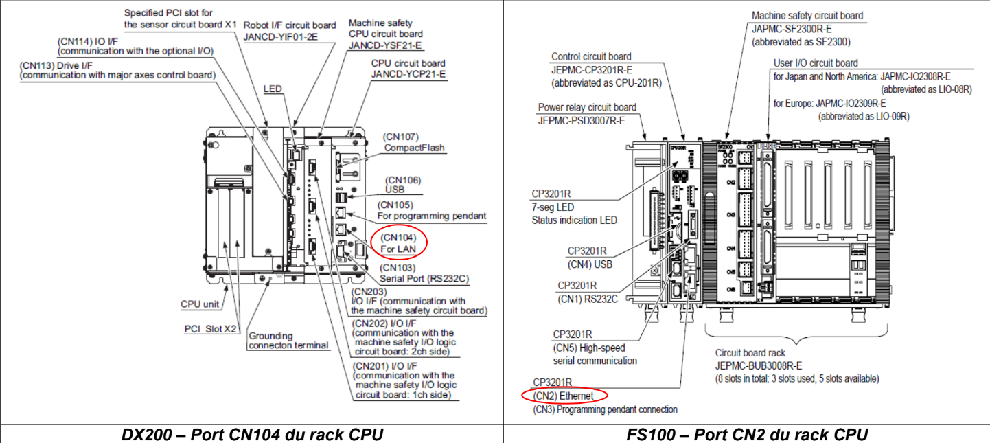
For DX200 controllers you need to connect the Pickit processor to the CN104 port.
For FS100 controllers you need to connect the Pickit processor to the CN2 port.
For YRC1000 (Micro) controllers you need to connect the Pickit processor to the CN106 or CN107 port.
IP configuration
Warning
Before making these changes, the robot controller should be in maintenance mode, and the security mode should be management mode.
Setting the IP address of the robot controller should be done in maintenance mode. Go to SYSTEM → SETUP → OPTION FUNCTION → LAN interface setting (or Network for DX200 and FS100) and set the following values:
IP ADDRESS SETTING: MANUAL SETTING
IP ADDRESS: 169.254.5.182
SUBNET MASK: 255.255.0.0
DEFAULT GATEWAY: 0.0.0.0
Press ENTER and CONFIRM to modify the values.
Load the program files
Before starting, Download the Pickit Yaskawa files here. The Pickit folder should be copied to a USB pen drive.
The robot controller should still be in maintenance mode and the security mode set to management mode before making these changes.
Insert the USB pen drive in the robot pendant.
Load the correct USB device under MotoPlus APL → DEVICE.
Select the folder Pickit > MotoPlus on the USB device under MotoPlus APL → FOLDER.
Load the MotoPlus application under MotoPlus APL → LOAD(USER APPLICATION).
Warning
In the next step, uploading the system data file MACRO INST DEF DATA, MACRO.DAT will remove all existing macro files on your controller, before pushing in the Pickit macros. If this is unwanted, do not upload the file. In that case, you should upload all other files as described below, and then manually define the macros.
Press Select, Enter and confirm. Now reboot the controller in normal mode with the USB device still attached. After rebooting, set security to management mode.
Load the correct USB device under EX. MEMORY → DEVICE.
Select the folder Pickit > Program on the USB device under EX. MEMORY → FOLDER.
Load the I/O DATA, SYSTEM DATA and JOB files under EX. MEMORY → LOAD (the order of loading the files is important).
Load the Pickit example jobs
In the Pickit folder there are two example jobs available. These can be uploaded to the controller so you can easily get started with picking.
Select the folder Pickit > Program > Examples on the USB device under EX. MEMORY → FOLDER.
Load the JOB files under EX. MEMORY → LOAD.
Setting the Pickit IP address on the robot controller
Still in normal mode, the IP address of Pickit needs to be entered in a String. To do this:
Go to Main menu → VARIABLE → STRING → S099.
Set S099 to value 169.254.5.180.
Note
There is no communication yet between the Pickit and the robot. So don’t worry if the connection is not shown in the Pickit web interface Top bar. The robot can be pinged from the Pickit web interface to check the IP settings. Details on testing this connection can be found on: Testing the Robot to Pickit connection.
Test the robot connection
To start the communication, you can run PIT_RUN on the robot. This job can be found in JOB → SELECT MACRO JOB.
While the program is running, an indicator in the Pickit web interface Top bar should confirm that the robot is connected .
Example program: TEST_CALIB
This example program can be found in JOB → SELECT JOB, and allows executing robot camera Calibration.
Define the tool
When using Pickit it is important that tool0 is set equal to the robot flange. This is done by setting all the values of tool0 to 0.
Set user frame
To help us set the user frame we are going to use a Position variable, by default P008. Set following values in VARIABLE → POSITION(ROBOT):
Select BASE.
Make sure that X, Y, Z, Rx, Ry and Rz are all equal to 0.
Here it is assumed that P008 is not yet being used anywhere else in the robot program. You can also use any other variable, as long as it is free. In that case, make sure to fill this variable in, in the command MFRAME UF#(5) P008 BF.
After running the program, a new user frame (5) will be created that will be used both for calibration and picking.
Teach calibration points
The calibration program requires five points to be defined. For more information on how to define these points, see the article on Multi poses calibration.
Execute the robot program
Before running the calibration program, make sure that the Pickit web interface is in the Calibration page, which provides feedback on calibration plate visibility and progress of the calibration process (more). To run this program either do Play + Start, Interlock + FWD or Interlock + Test.
Example program: TEST_SIMPLEPICK
This example program can be found in JOB → SELECT JOB.
The idea of the program is the following: First, a detection is triggered. If an object is found, the robot moves to the object to pick it, and drops it off at a fixed position. Once the robot is out the field of view of the camera, a new Pickit detection is immediately triggered. If the ROI is empty, the program stops.
Define the tool
Create a tool frame with the actual TCP values. Again it is important that tool0 is not changed. Any other tool can be used.
Set PIT_CFG
In this command the following values have to be set:
Setup: Pickit setup file ID.
Product: Pickit product file ID.
User Frame: User frame that was created in TEST_CALIB. By default, this is 5.
Tool: Number of the tool frame defined in the previous step.
Note
If something is wrong here, you can expect the following message: Undefined user frame. The example program by default uses frame 5 and tool 1, but these might not exist.
Set robot positions
C00000: Home: Starting position of the robot. This position needs to be defined by the user.
P025: Detect: For a fixed camera mount, this position should not occlude the camera view volume, while for a robot-mounted-camera it should place the camera so it fully captures the desired view volume.
P023: Above pick area: A transition position to enter the pick area. This position needs to be defined by the user.
LP000: Pre pick: This position does not need to be defined.
P099: Pick: This position does not need to be defined.
LP001: Post pick: This position does not need to be defined.
P029: Dropoff: A position where the parts will be dropped. This position needs to be defined by the user.
Note
The positions P023-P029 can be changed in the position variable menu.
Add grasping/releasing logic
At the Pick and Dropoff positions, grasping and releasing logic needs to be added, respectively.
Execute the robot program
To run this program either do Play + Start, Interlock + FWD or Interlock + Test. Happy picking!
Variables used by the Pickit system
Variable |
Field name |
Comment |
|---|---|---|
I099 |
command |
A single command from robot to Pickit. |
I098 |
setup |
A number matching to a setup file known by the Pickit system. |
I097 |
product |
A number matching to a product file known by the Pickit system. |
I096 |
Frame ID |
A number matching the frame ID used during calibration and picking. |
I095 |
Tool ID |
A number matching the tool ID used for picking |
I094 |
Timeout |
Value of the timeout used for communication with Pickit |
I091 |
object_type |
The type of detected object. |
I090 |
status |
Contains the Pickit status or a response to previously received robot commands. |
I080-089 |
status of cycles |
Used for keeping track of the communication cycle with Pickit. |
S099 |
IP Pickit |
IP address of Pickit, by default 169.254.5.180. |
P099 |
object_pose |
An object pose expressed relatively to the robot base frame. |
P098 |
object_dimension |
[0]: length or diameter (m) [1]: width or diameter (m) [2]: height (m) |
D091 |
object_remaining |
If this field is non-zero, it contains the number of remaining objects that can be sent in next messages to the robot. |
D090 |
object_age |
The amount of time that has passed between the capturing of the camera data and the moment the object information is sent to the robot. |
Tip
If these registers are already used on your robot, please contact us at support@pickit3d.com, and we will assist you in finding a solution.