Warning
You are reading the documentation for an older Pickit release (2.4). Documentation for the latest release (4.1) can be found here.
Robot tool model
Pickit allows to model the robot tool that is used for picking. Defining a tool model is not mandatory, but highly recommended for the following reasons:
In constrained picking scenarios like bin picking, it’s possible to prevent collisions between the robot tool and the bin or other objects.
When defining pick points, it’s helpful to visualize the robot tool with respect to the object to confirm the correct placement of a pick point.
Attention
Pickit is not aware of the robot Tool Center Point (TCP) definition. Make sure that you define a correct TCP in your robot, such that the real tool and the Pickit model are well aligned.
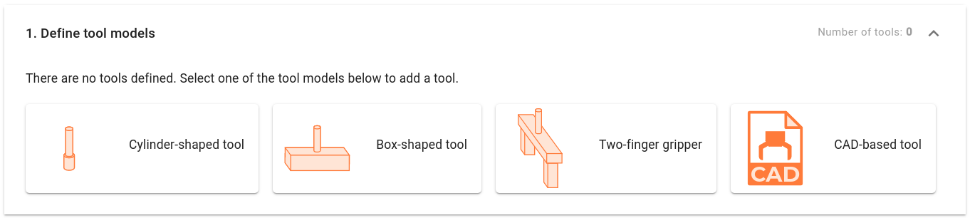
The Picking page exposes different alternatives for defining the robot tool model.
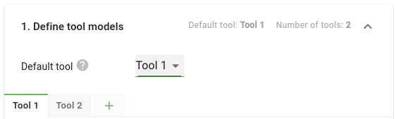
If your application requires it, it’s possible to create multiple tool models, and assign different tools to different pick points. A common example would be a two-finger gripper used with different opening distances depending on the selected pick point.
When multiple tools exist, the default tool represents the tool that will be selected when a new pick point is created.
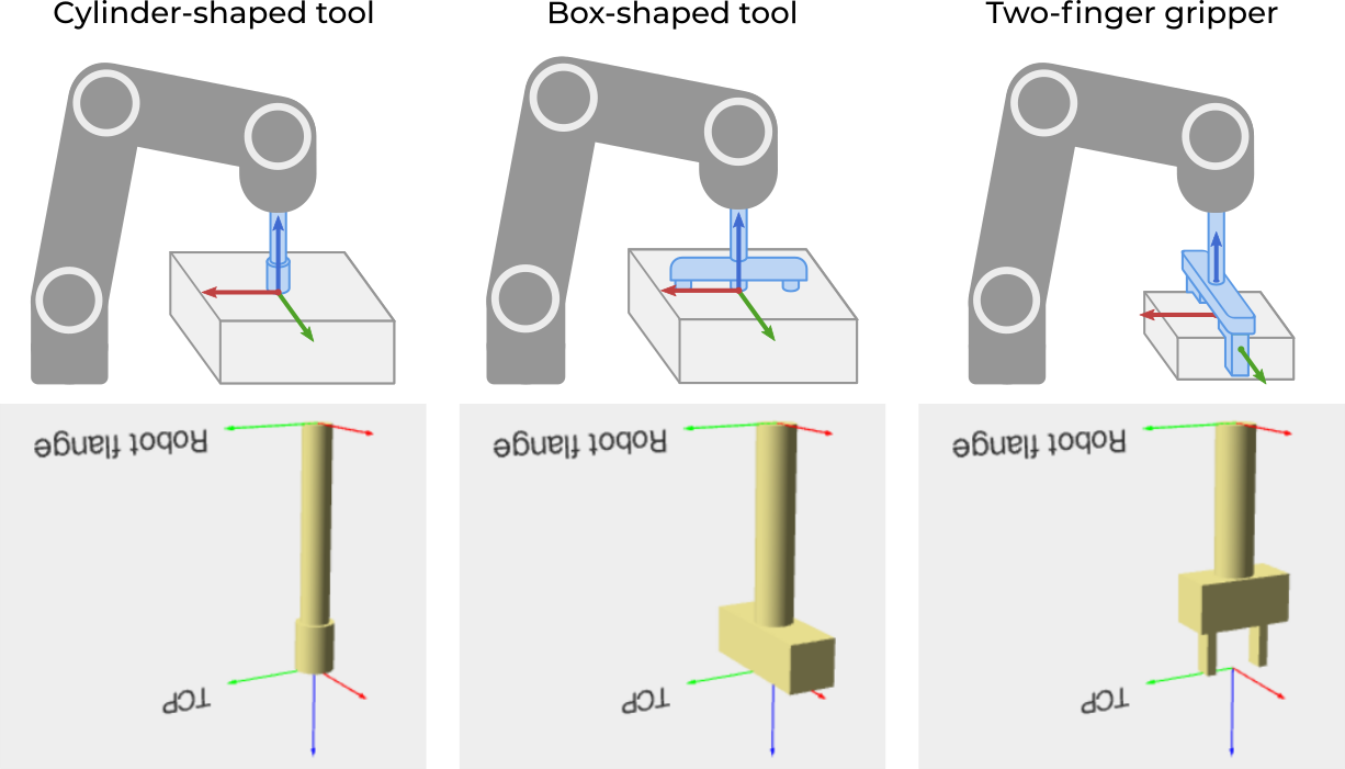
Generic tool model
Pickit provides the following general purpose models that closely resemble commonly used tools:
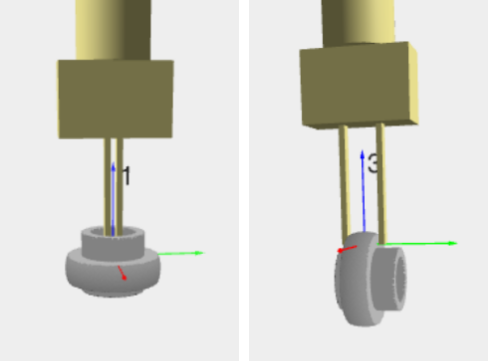
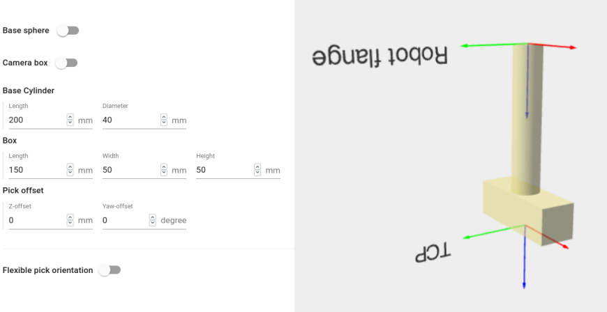
It is possible to modify a tool’s characteristic dimensions, as well as adapt its relative distance and orientation with respect to an object’s pick point. The image below shows the tool model editor for the Box-shaped tool.
Tip
It is recommended that the robot tool model is slightly larger than the actual tool, to have a safety margin when performing robot motions. If the model is too large (too conservative), objects will be labeled as unpickable even if they could be picked without collision. Conversely, if the model is smaller than the actual tool, unpickable objects might be labeled as pickable and the robot will collide when picking them.
Tip
When representing tools like suction cups, it is acceptable that the flexible bellows collide with the object to pick.
In these cases, it is recommended to not model the last millimeters of the tool tip, for instance, make the tool tip shape 5mm shorter and set the Pick offset in Z to 5mm.
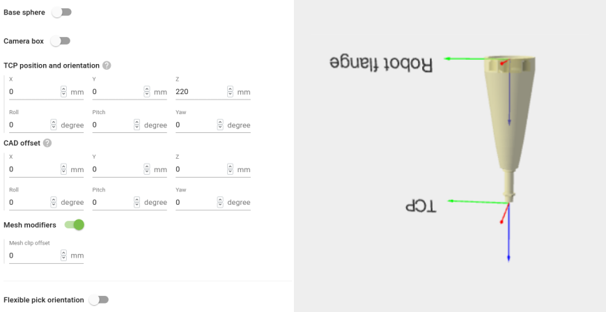
CAD-based tool model
If you have a CAD file of the tool, you can directly upload it to Pickit. This is a very convenient way to get your robot tool model into Pickit, as you only need to specify:
The CAD file to upload.
The units in which the CAD geometry is represented.
The location of the Tool Center Point (TCP) with respect to the flange.
Optional: An offset to apply to the CAD model. If the model origin coincides with the flange frame, it doesn’t need to be specified.
Optional: The mesh clipping offset, which cuts off the bottom-most part of the CAD model by a user-defined amount. This is useful for not including parts of the CAD model close to the TCP in collision checks.
Note
Pickit only supports the stl format for tool models. This format is widely supported and most CAD design editors can export CAD into stl format. There are also free online converters available on the Internet which can help you in doing so.
Tip
To speed up collision checks between the tool model and the bin or other objects, follow these recommendations when preparing your CAD file:
Remove all non-visible geometry such as inner walls. They slow down collision checks without adding any value.
Reduce the complexity of the CAD geometry. A typical model should not exceed a few thousand faces.
Optional tool configuration
Flexible pick orientation
In practice, many tools can tolerate some variation with respect to the nominal pick orientation without compromising pick success. Pickit represents these variations as a tool’s flexible pick orientation, and taking advantage of them can increase the likelihood that an object is pickable.
Additional collision geometries
The robot tool model can also include additional optional geometries:
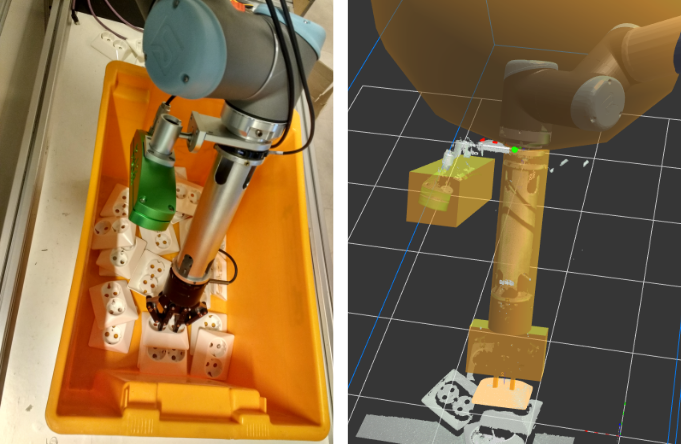
The Base sphere, which typically contains the robot wrist, helps preventing collisions when part of the robot enters (or gets very close to) the bin.
The Camera box, which represents the camera volume in robot-mounted camera setups, makes sure that the mounted camera does not suffer any collisions.
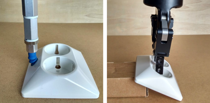
The example below compares the actual robot tool with the model used by Pickit. It shows the two-finger-gripper generic model representing a gripper attached to a long extension cylinder. It uses both the optional Camera box and Base sphere around the robot wrist.