Warning
You are reading the documentation for an older Pickit release (3.2). Documentation for the latest release (4.1) can be found here.
Your first detection
In this article you will learn through a simple example how to inform Pickit about:
Where to pick parts from.
What to pick as part.
How to pick it with your robot tool.
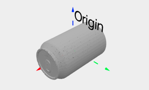
We will be picking a soda can from its cylindrical surface. We have chosen this part since it’s a widely and easily available item.
Check camera field of view
As a preliminary step, let’s confirm that the camera field of view contains the desired Region of Interest (ROI), that is, where parts are expected to be detected and picked:
Open the Pickit web interface.
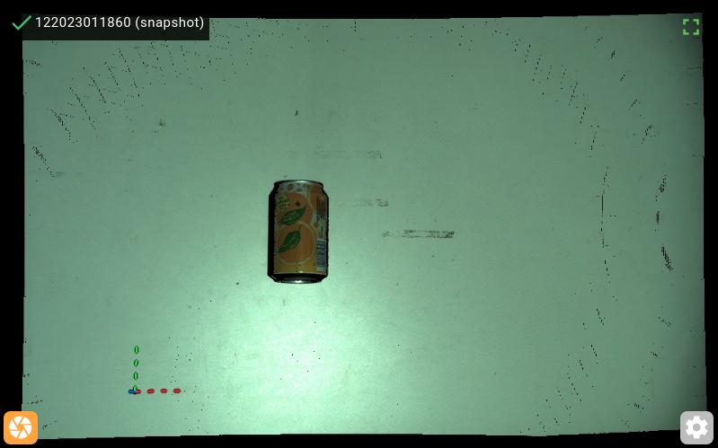
Navigate to the Setup page, and open the Build ROI box section. The 2D view should show a live stream of what the camera is seeing.
Place a soda can rolling on its side in the region where you expect to pick it, and confirm that it is visible in the 2D view.
If the soda can and its surroundings are correctly visualized, continue to the next step, otherwise perfrom the additional checks:
If the 2D view displays
No active camera, check that your camera is correctly connected.If the image is black, or the visualized location is not what you expect, check the camera location. In particular, for a robot-mounted camera, make sure that the robot is correctly positioned image captures.
Where to pick
In this section we will inform Pickit about the region where we expect to find parts to pick, or Region of Interest.
If robot mode is enabled in the web interface, click Disable Robot Mode in the top bar.
Navigate to the Setup page.
Create a new setup file by clicking + New on top of the page, name the file
test_pickit, and click Create.Expand the Build ROI box section of the Setup page.
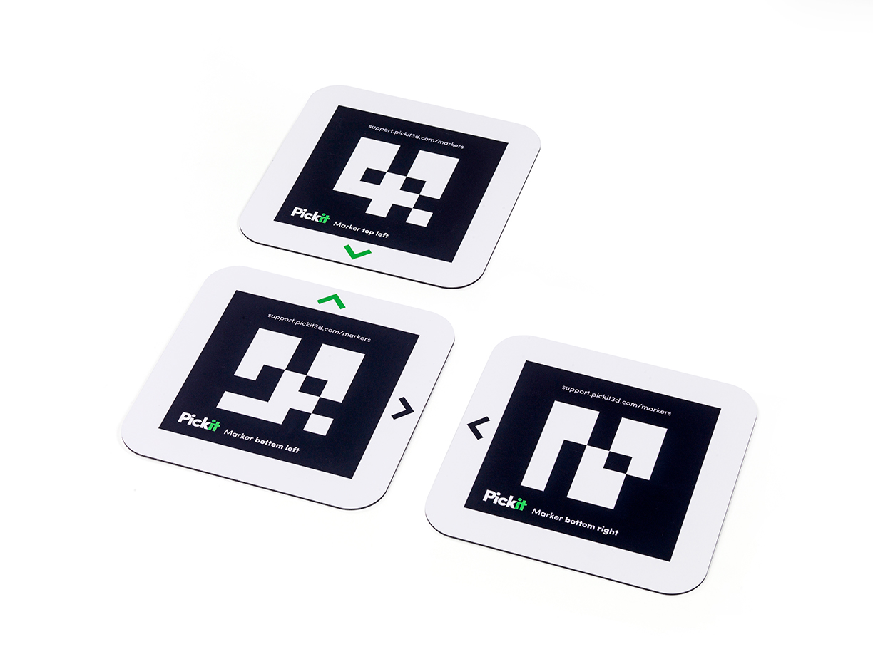
Take the three ROI markers and lay them out in an “L” shape, such that the black and green arrows align as shown below.
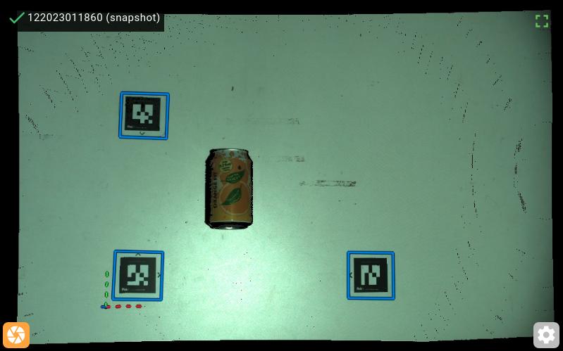
Place this “L” shape inside the camera field of view, and around the region where the soda can is located. In the 2D view, you should expect to see the outline of all three markers highlighted in blue.
Tip
If this is not the case, check that there are no light sources causing strong reflections in the marker surface, and that the camera is not too far from the markers.
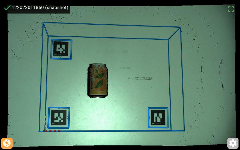
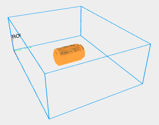
In the Build ROI box section, click Around QR markers. This button is only enabled when all three markers are visible. Wait until the ROI box is updated.
You should expect to see a blue box around the three marker locations, as shown below. From this point on, you can remove the ROI markers from the camera field of view.
Press the Save button on top of the page to save the changes to the setup file.
What to pick
In this section, we will teach the shape of the part to pick, the soda can. Pickit supports multiple ways of doing this:
Upload a CAD model.
Use a cylinder primitive, and only model the cylindrical section of the can.
For this example, we will use the CAD file of a 33cl can with diameter 66mm and height 115mm.
Note
You can also perform this exercise with a soda can of different dimensions, or with a more complex part, case in which you need to either provide your own CAD file, or use one of the alternative methods mentioned above.
Download the CAD model of the can: soda_can_66x115_mm.stl
Navigate to the Detection page.
Create a new product file, by clicking + New on top of the page, name the file
test_pickit, and click Create.In the Define models section, select Teach from CAD, and upload the can model.
You should expect to see a 3D visualization of the can model.
Press the Save button on top of the page to save the changes to the product file so far.
Tip
You can already verify if the can is detected. Place it in the camera field of view, press the Detect button below the viewer, and inspect the objects view and objects table. Note that at this point, all valid detections will be displayed as unpickable (in orange) because the model doesn’t have any pick points defined yet.
How to pick
In this section, we will inform Pickit about how to pick the part and the robot tool to do it with.
Navigate to the Picking page.
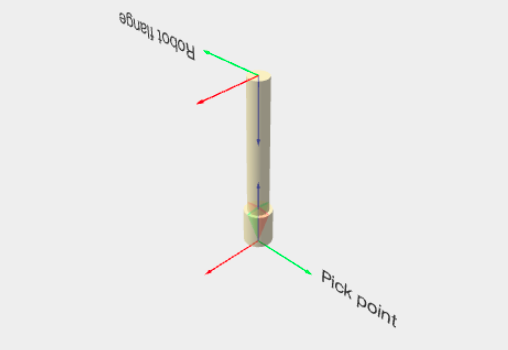
In the Define tool models section, click on Cylinder-shaped tool. You should see a 3D visualization of the tool, where you can optionally modify its shape and dimensions.
Note
In this simple exercise, the tool model is used only for visualization and demonstration purposes. In more complex scenarios like bin picking, it can be used for collision prevention against obstacles like bin walls or its contents.
In the Define pick points section, click on + Add pick point.
Expand the newly added Pick point 1 to show the different properties that are available
Position the pick point on the can surface by setting the point location to be at 33mm (the can radius) along the Z axis.
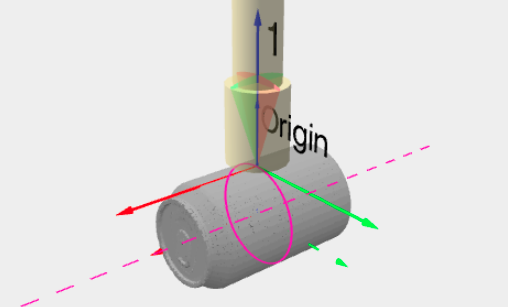
Since the part is axisymmetric, enable the symmetry axis option. Its default location should be correct for the can, so there’s no need to modify it. Picks along the shown magenta circle will be equally valid.
You should see a 3D visualization of the can, the pick point, the symmetry axis, and the robot tool at the pick point, as shown below.
Press the Save button on top of the page to save the changes to the product file.
Test part detection
Place a soda can in the camera field of view, inside the ROI.
Press the Detect button below the viewer.
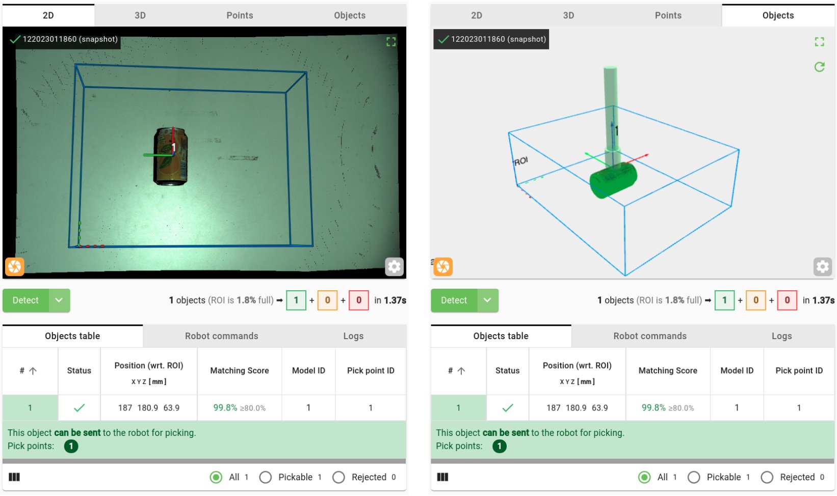
You should expect the can to be detected. You should be able to see:
The pick point highlighted in the 2D view.
The pick point and the can model in the objects view.
Quantitative information about the detected object in the objects table.
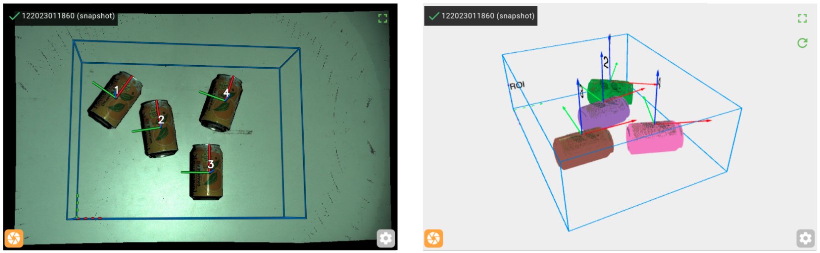
Play around: Roll the soda can over to different locations within the ROI, or add multiple cans and run further detections.
Congratulations on your first detection! You’re now ready to the next step, and move on to your robot for performing your first robot-camera calibration.
Tip
You can learn more about these topics in the following sections of this knowledge base:
Setup section, and where to pick video tutorial.
Detection section, and what to pick video tutorial.
Picking section, and how to pick video tutorial.