Warning
You are reading the documentation for an older Pickit release (2.3). Documentation for the latest release (4.1) can be found here.
Single pose calibration
Single pose calibration can only be performed if the camera is fixed at a static location, and not if it’s mounted on the robot flange. Furthermore, the robot needs to have either a 50 mm (ISO 9409-1-50-4-M6) or 31 mm (ISO 9409-1-31.5-4-M5) wide flange.
If any of the above requirements are not met, you should use Multi poses calibration instead.
This article describes the main steps in the single pose calibration procedure:
Mounting the calibration plate
The advantage of only one pose required for robot-camera calibration comes at the cost of Pickit needing to know how the calibration plate is mounted with respect to the robot flange. Therefore, the plate should be mounted to the flange in a specific way. Installing the Pickit calibration plate describes the correct way to mount the plate to the flange.

Determining the helper transformation
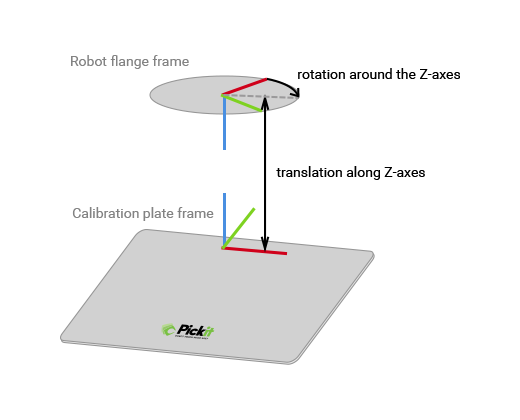
In the Pickit web interface, you need to specify the helper transformation, which is the transformation between the flange frame of the robot and the calibration plate frame. The figure below shows the defined calibration plate frame.

If the screw holes of plate and flange are aligned, this transformation consists of:
a translation along the Z-axis,
a rotation around the Z-axis.
If the calibration plate is screwed directly to the flange, and oriented according to Installing the Pickit calibration plate, the helper transformations in the table below apply, for the following robot brands:
Robot brand |
Translation in Z |
Rotation around Z |
|---|---|---|
Universal robots |
0 mm |
45 ° |
Fanuc |
0 mm |
135 ° |
KUKA |
0 mm |
-45 ° |
Stäubli |
0 mm |
135 ° |
ABB |
0 mm |
-45 ° |
Yaskawa |
0 mm |
-45 ° |
If the calibration plate is attached to the robot flange through a tool changer or a tool, then the translation along Z is the distance between the plate and the robot flange.
Building the robot program
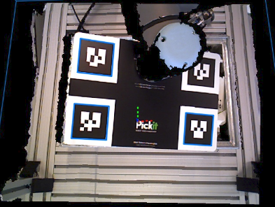
In the robot program, the robot should first move to a waypoint where the mounted calibration plate is shown to the Pickit camera approximately in the center of the 2D image, and close to the picking area. Make sure the plate is visible in the 2D viewer. Afterwards the program should request Pickit to find the calibration plate.

Calibrating
Click on the Calibration button, located on top of the Pickit web interface.
Choose the fixed camera mount, since single pose calibration does not support the robot mounted option.
Select the correct robot type: 6 DOF or 4 DOF, depending on the number of degrees-of-freedom of your robot. If your robot has only 4 degrees-of-freedom, fill in the distance between calibration plate and robot flange in the field Flange Z-axis.
Choose the single pose robot-camera calibration method.
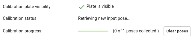
Go through the instructed steps, and run the robot program. You can see the status of the calibration process in the Pickit web interface.
Important
After finishing robot-camera calibration, don’t forget to check the calibration result. Go to Checking robot-camera calibration to know how.