How to use Pickit Pattern
Just like the Flex detection engine, the Pickit Pattern detection engine has a typical workflow, which is described in step by step in this article.
Note
By default the Pickit Pattern engine is not exposed in the web interface. To enable it, open the Settings, navigate to Advanced settings > Application-specific engines and turn on the Enable Pattern engine toggle.
Define the 3D scene
The first step of Pickit Pattern is to define where the Pickit system should look. The 3D scene is defined by a Region of Interest and the optimize detection parameters. These detection parameters are explained in the article Explaining the Pattern detection parameters.
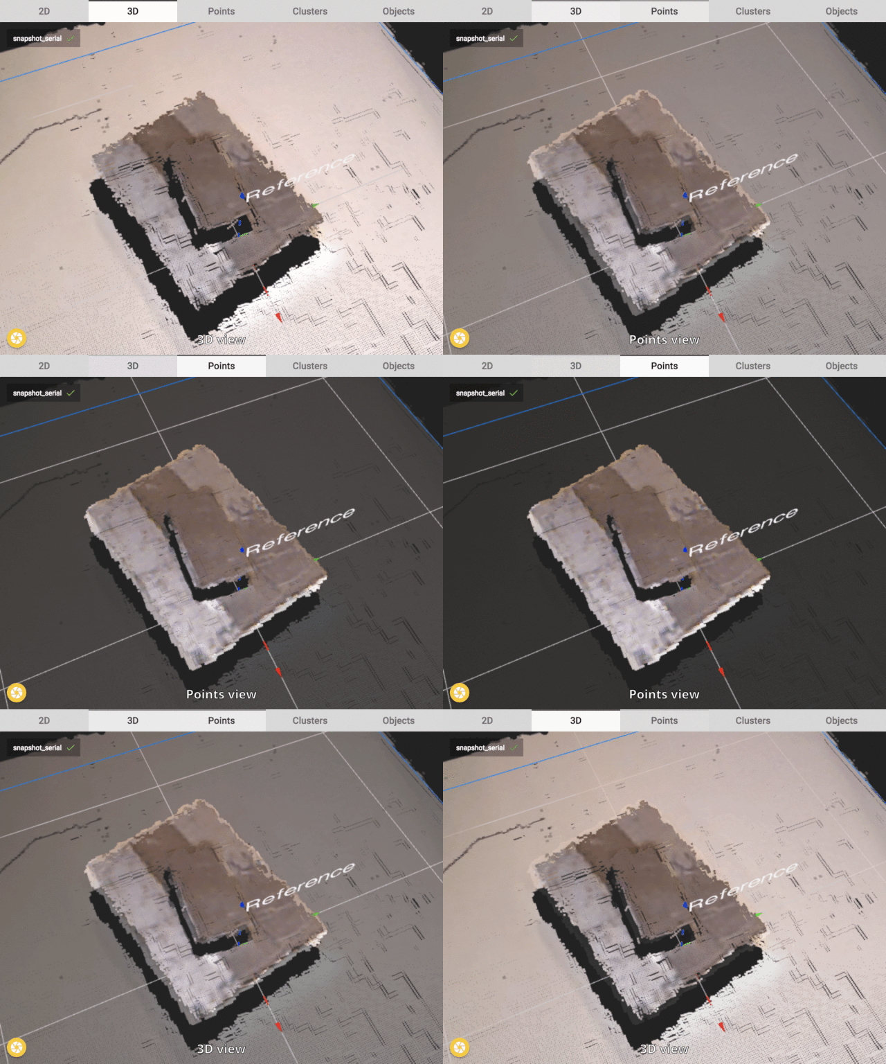
In the image below an example of a good defined scene is shown. First, in the 3D view all points within the field of view of the camera are shown. Second, in the Points view only the points of the parts are shown. The table is filtered out.
The information shown in the Points view is what will be transferred to the next step. All other information is not taken into account for the detection with Pickit Pattern.

Divide the scene into clusters & reject (some) clusters
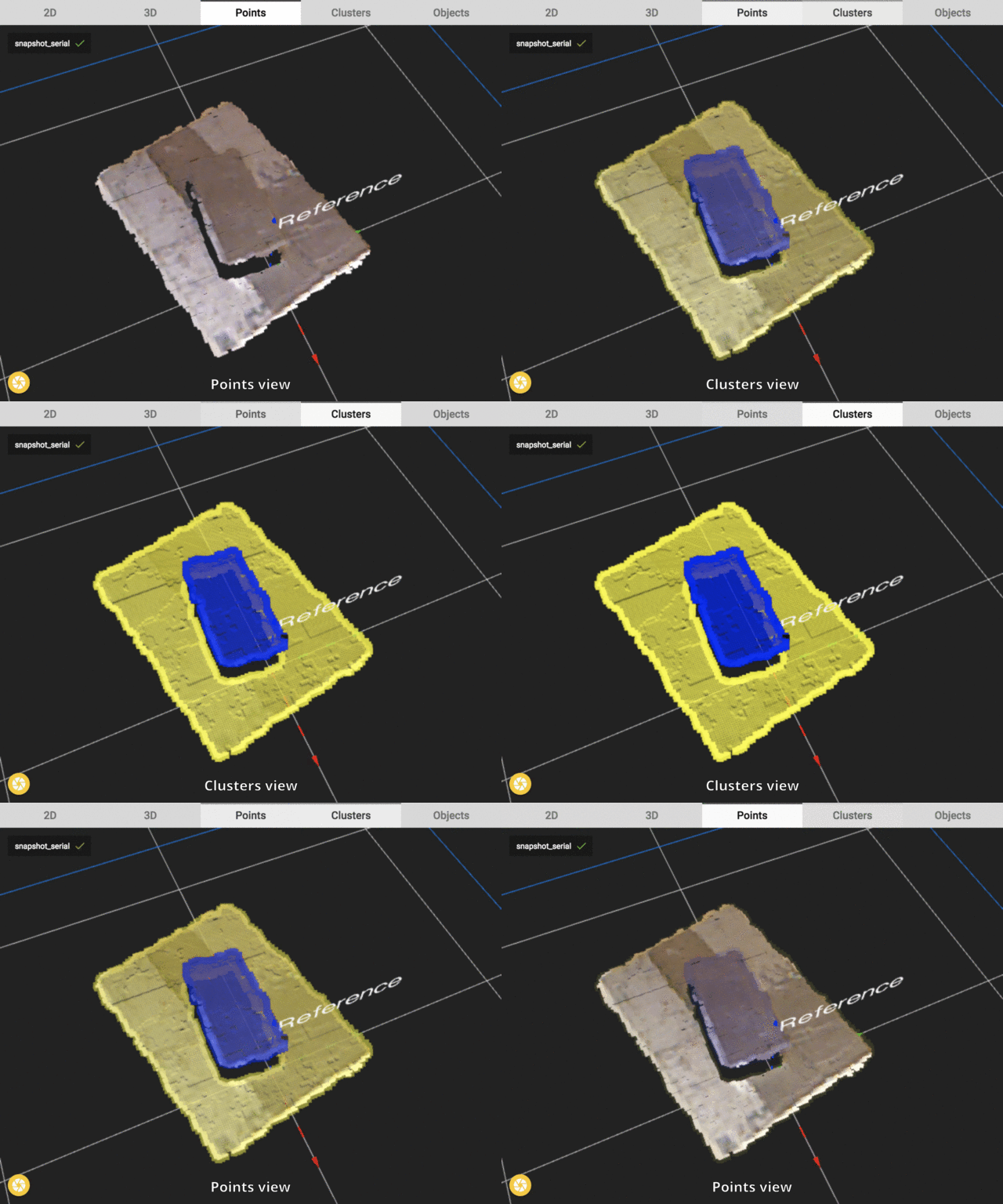
The next step in the Pickit Pattern detection is to divide the scene into smaller different parts (clusters). Each cluster contains all points of one layer in the scene. All clusters are shown in a different color.
In the image below the effect of clustering is visualized. The 3D scene is now divided into 2 different clusters (shown in different colors). In this step also the rejecting of clusters can be applied. For instance one of the two planes could be rejected based on the size or dimensions of the plane. But in this example this is not necessary so no rejecting is done.
The boundary of a planar cluster is known as its contour. In the Clusters view, contour points can be distinguished from inner cluster points by its thickness. The 2D shape model is fit to this contour, and therefore the quality of the match depends on the quality of the contour. Parameters that have an influence on contour points are explained in Fit objects to clusters.

Difference of clustering between Pattern and Flex
When using Pickit Flex, it is important that each cluster represents a different object. Pattern, on the other hand, allows that one cluster contains mutliple objects, hence being the preferred choice when objects are aligned and touching.
Define dimension and orientation of objects
In this additional step the user defines the size and the orientation of the objects in the scene. In following article all parameters on how this can be defined are explained, Explaining the Pattern detection parameters.
Fit & filter objects
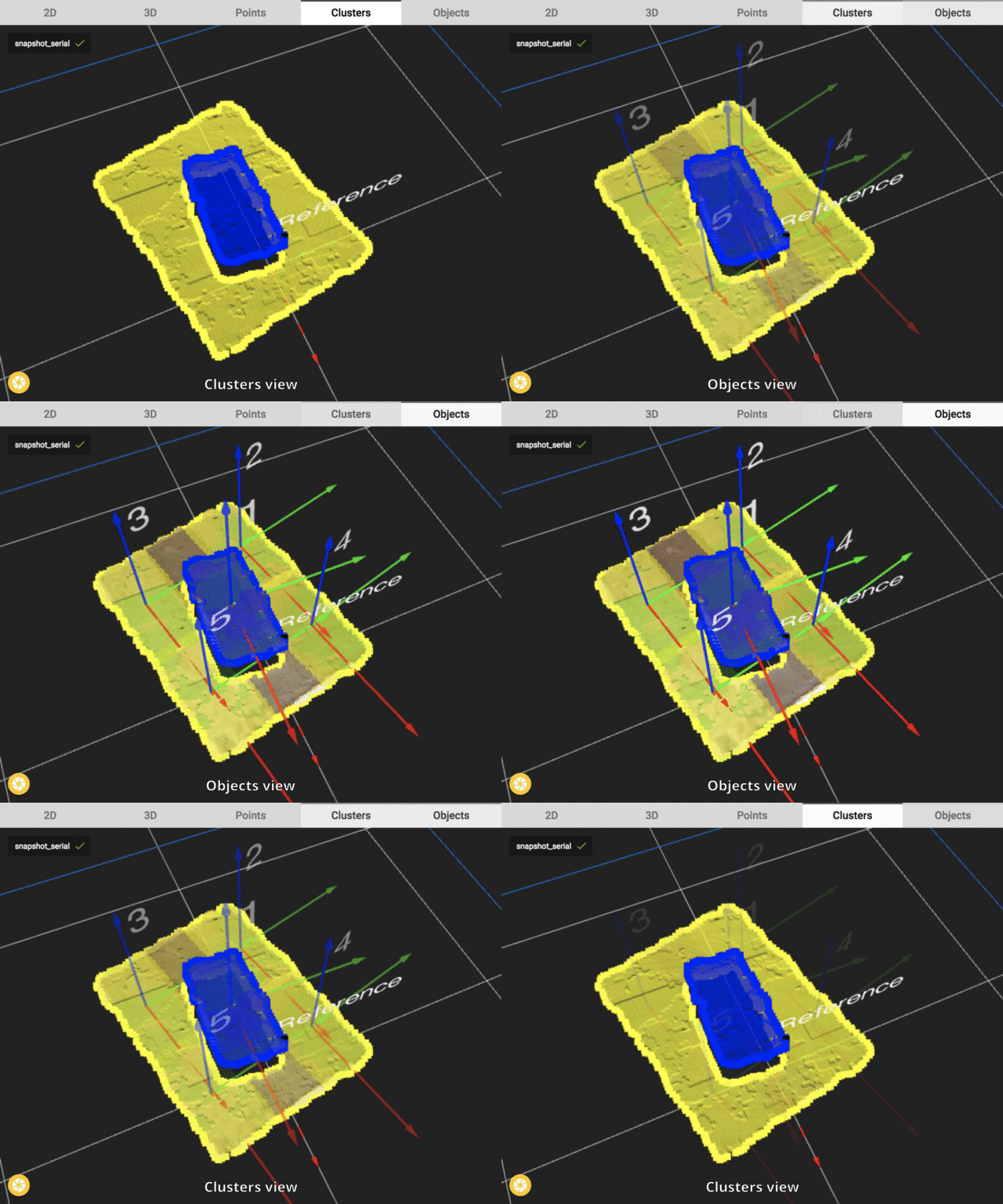
The final step of Pickit Pattern is to fit the defined fixed size shape from the previous step. This fixed size shape is fitted to the cluster contour. Good fits can be sent to the robot one by one.
In the image below we see four good fits. In the top layer a single object is fitted. In the bottom layer a shape is fitted in all four corners. Once all these blocks are removed by the robot, a detection for the last two blocks is possible.
