How to reject detections that deviate from an expected object location?
Motivation
Non-pick-and-place applications like surface treatment (sanding, deburring) and dispensing (gluing, sealing) require detecting a single part whose location is roughly known in advance and performing an operation on it.
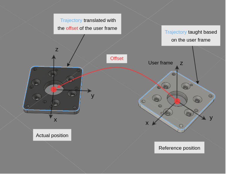
The typical way to set up these applications is that first, robot trajectories for executing the operation are defined with respect to a user frame, which is attached to the part. Then, Pickit is used to pinpoint the part location and update the user frame, enabling the execution of robot trajectories relative to the current part location.
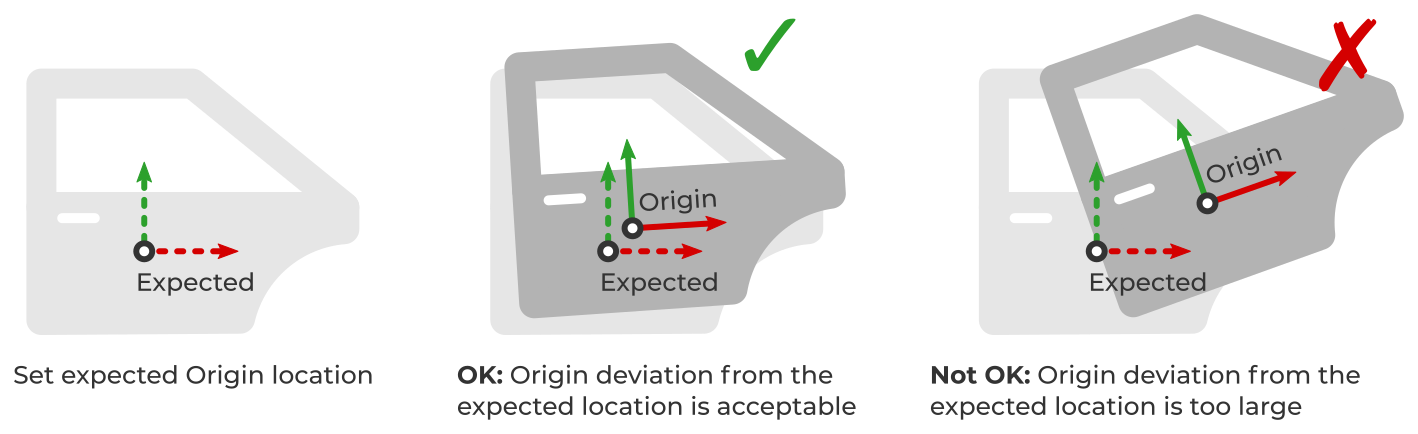
In such applications, it is often required to reject parts that deviate too much from an expected location. For example, if the part is too far from the robot, too tilted, or even upside-down for some reason, the robot might need to reach beyond its workspace, or violate some other application constraint. By identifying and rejecting parts with an unexpected location, the application logic can take the correct action, such as raising an alarm, instead of attempting to execute an unwanted operation.
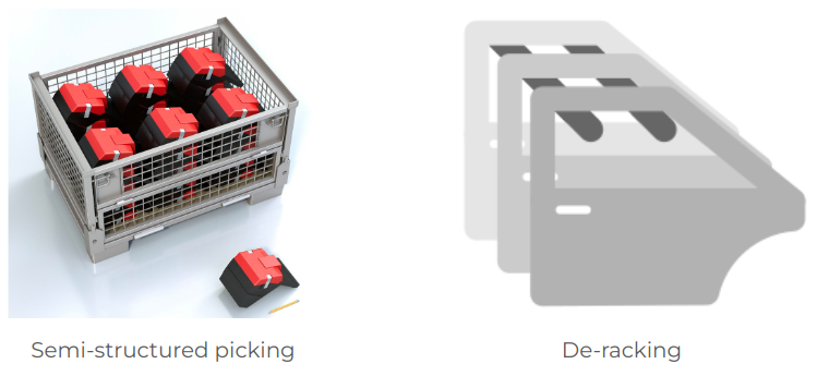
In specific picking applications like semi-structured bin picking or de-racking, parts can also be located at an expected orientation, for example, as shown below.
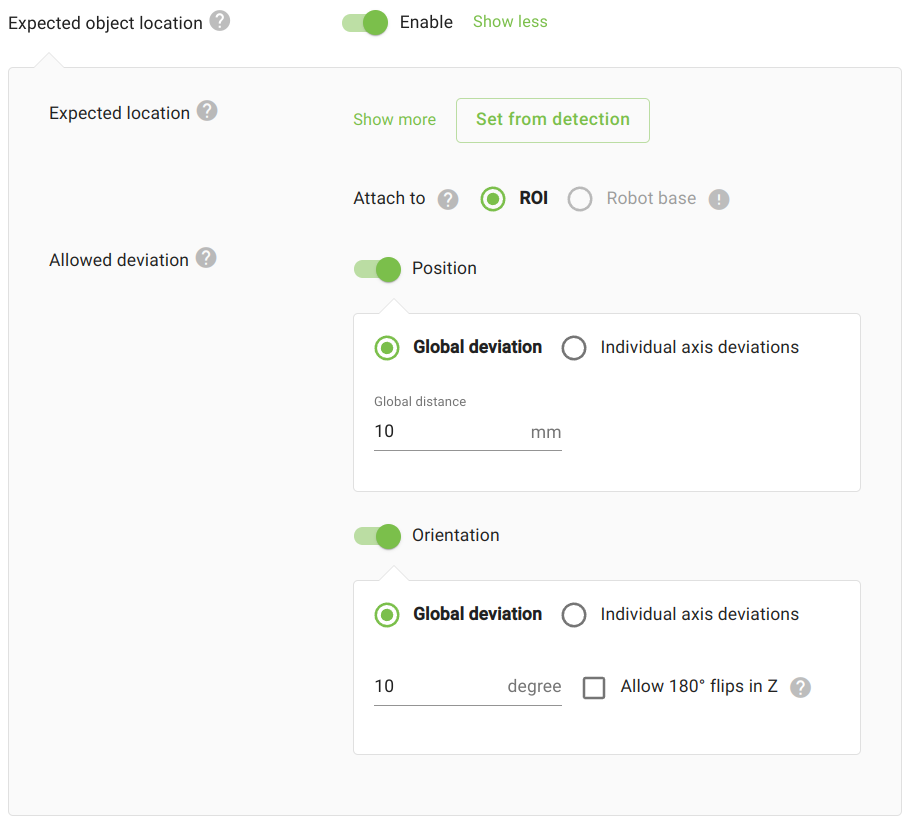
Expected object location filter
The expected object location filter is used to reject parts that deviate too much from an expected location.
The typical workflow for using the filter is as follows:
Detect an object in the expected location.
Enable the filter from the Filter objects in the
Detectiontab.Specify the expected location for the part.
We recommend using the
Set from detectionbutton, which sets the location from the first valid detection reported in the objects table. You can then fine-tune the location by setting exact values or using the interactive drag handles.Set the attachment (ROI or robot base).
The expected location will be specified with respect to this attachment and remain fixed to it. For example, if attached to the ROI and the ROI origin moves, the expected location will move along. We recommend setting the attachment to the robot base, which requires a valid calibration to exist.
Set the allowed deviation from the expected location, in position, orientation, or both.
Run detections with parts at different locations to test the filter.
Tip
The expected location is specified for the model Origin, and you can set a meaningful location for this frame with respect to your part.
Be mindful that if you do this, you will probably have to reset the filter’s expected location value.
You can see the expected location and the model origin for each object from the Objects view.