Warning
You are reading the documentation for an older Pickit release (3.0). Documentation for the latest release (4.1) can be found here.
Multi poses calibration
Multi poses calibration is the recommended method for performing robot-camera calibration in Pickit. With this method, the robot shows the calibration plate to Pickit from five different viewpoints.
Tip
You can learn about the main ideas behind multi poses robot-camera calibration by watching this video tutorial.
The placing of the calibration plate and the five poses from which it is detected depend on the camera mount.
Fixed camera mount
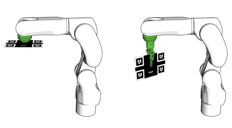
If the camera is fixed to a static structure, the calibration plate must be attached to the robot flange. It does not matter how the plate is mounted, as long as it’s rigidly attached to the flange. It can be, for instance, directly attached to the flange (below left) or grasped by the robot gripper (below right). You should not attach it, for instance, to a suction cup with flexible bellows, as the plate will wobble.
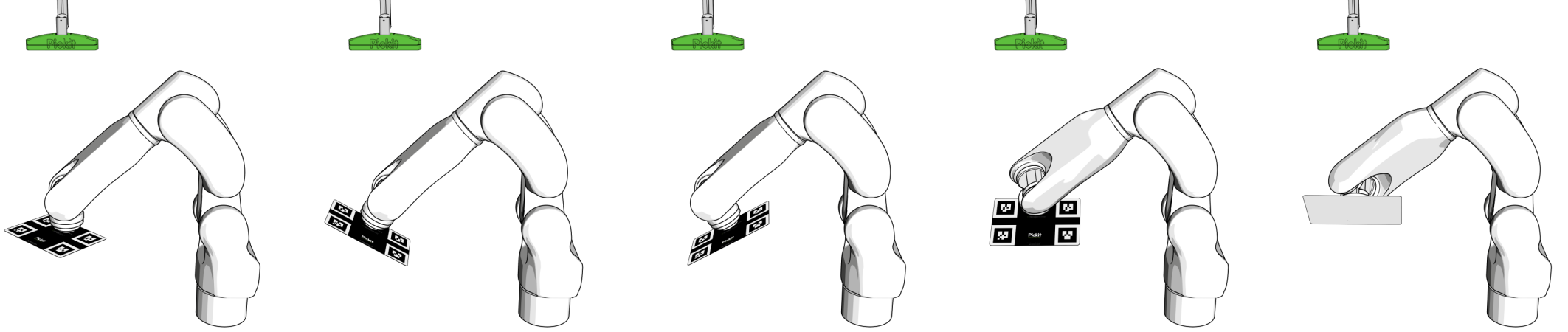
The five calibration poses are such that:
The calibration plate is at a distance to the camera similar to the distance at which parts are expected to be picked.
The plate is visible in the central region of the 2D camera image. Avoid markers close to the edge of the image.
The calibration plate is detected by Pickit.
One of the five poses is parallel to the image plane, and rotated within this plane (below left).
The remaining four poses are tilted with respect to the image plane by an angle of approximately 30°.
The order in which the poses are captured is not important.
Robot mounted camera
If the camera is mounted on the robot flange, place the calibration plate on a surface, at a distance to the camera similar to the distance at which parts are expected to be picked.
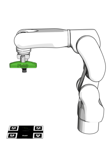
The simplest choice is to place the plate in the region where picking will take place (as shown above), but it’s also possible to fix it to a wall or other rigid structure next to the picking area. The latter is useful when executing calibration and validation autonomously from the robot, without human intervention.
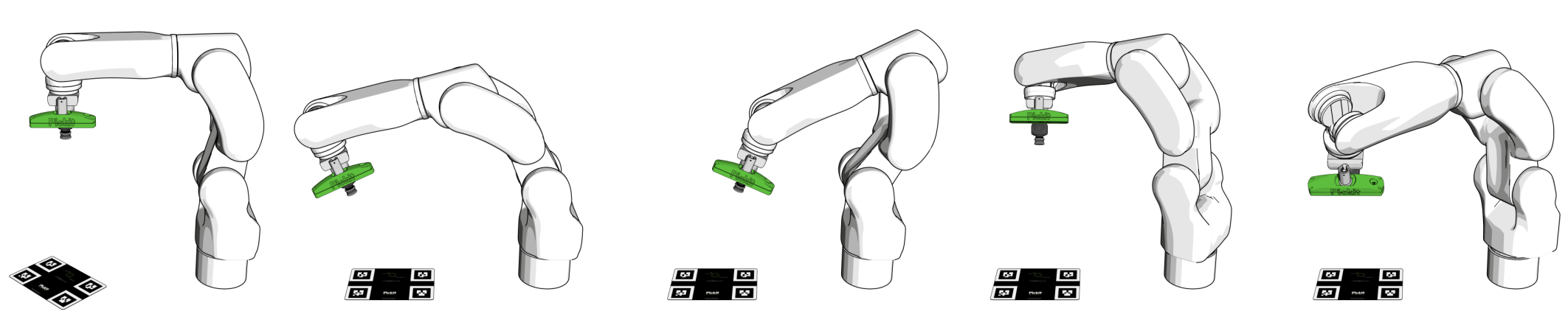
The guidelines for the five calibration poses are similar to those for a fixed camera mount. The only difference is that in this case it is the camera that rotates and tilts, and not the plate.
Calibrating from the web interface
To perform a new calibration, click the Calibration button on the top bar of the Pickit web interface, and then Start calibration to open the calibration wizard.
Select the camera mount (fixed or robot mounted) and robot type (6/7-axis standard robot or 4-axis palletizing robot).
Place the calibration plate and confirm that it’s visible in the camera view.
Collect the calibration poses.
Validate calibration. In this last step, you can optionally check the correctness of the calibration result (learn more).
During pose collection (step 3 above):
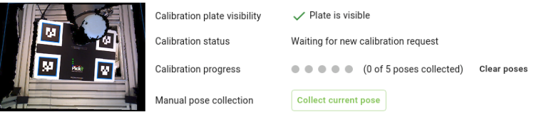
You should see a visual confirmation in the viewer and under
Calibration plate visibilitythat the calibration plate is visible at the pose.Under
Calibration progress, you should see an indicator that informs you how many poses have been collected so far.You can restart pose collection by clicking on Clear poses.
Most robot integrations allow collecting calibration poses manually. When this is the case, you can jog or free-drive the robot to the next calibration pose and click Collect current pose.
If your robot integration doesn’t support manual pose collection (Collect current pose is not shown), you should write a robot program that takes care of this, as exemplified here.
Calibrating from the robot
If you perform calibration often, it’s possible to run calibration autonomously from the robot, without using the Pickit web interface. Refer to the example calibration program, and the documentation of your robot integration to learn more.
4-axis palletizing robots
Palletizing robots have four actuated axes that allow the end-effector to be positioned in 3D space and rotated parallel to the ground plane. That is, the end-effector always points down to the ground plane and cannot tilt away from it, like a 6-axis robot.
If you have a 4-axis palletizing robot, in the last step of the calibration wizard, an additional input that depends on the camera mount is required:
Fixed camera: The vertical distance between the robot base and the camera.
Robot-mounted: The distance between the robot flange and the camera. Notice that, if the camera is mounted at a higher location than the robot flange, this value should be negative.
Tip
Looking at the camera location in the 3D viewer will help you obtaining the correct value.