Warning
You are reading the documentation for an older Pickit release (3.0). Documentation for the latest release (4.0) can be found here.
How to use Pickit Teach
This article describes how to get started with the Pickit Teach engine. Pickit Teach is a detection engine which can search for objects based on a previously taught model of the object.
Teach a model based on your part
Pickit provides three ways to teach a model of your part:
Teach from CAD: upload a Computer Aided Design (CAD) file of your part.
Teach from camera: show an object to the camera to teach its shape.
Teach cylinder: specify cylinder dimensions.
Detecting objects
Now that you’ve added your models, it’s time to detect objects.
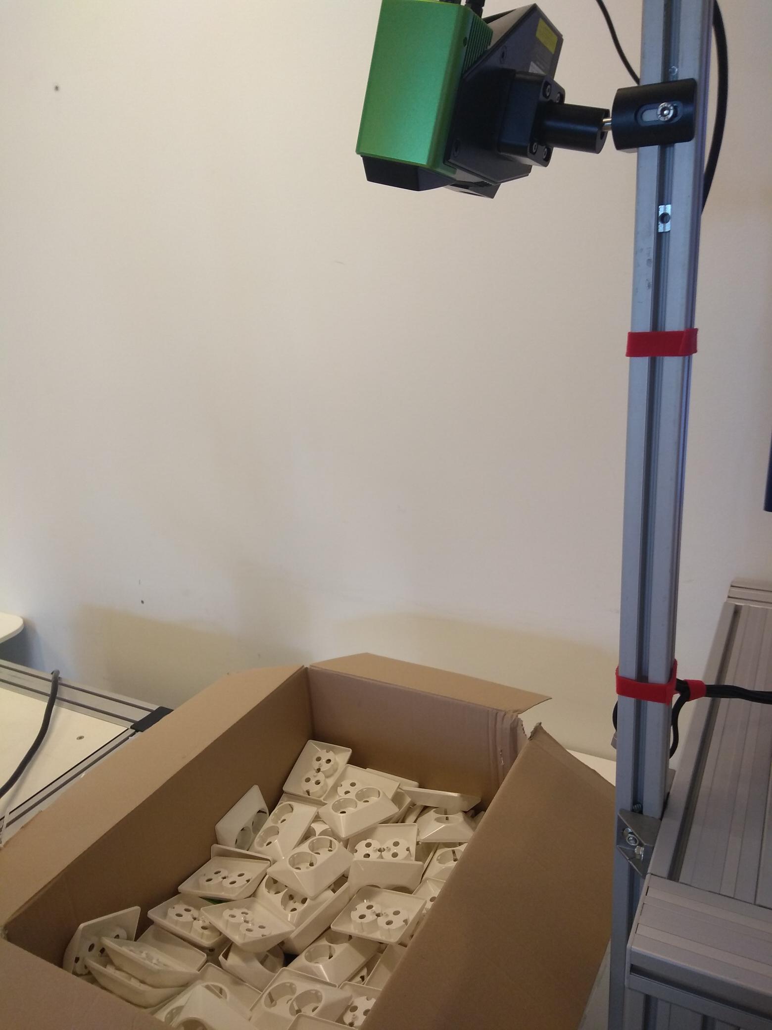
Place your objects below the camera as shown below, build a new Region of Interest box and press the Detect button.

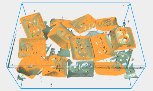
At this point, it’s possible to verify in the Objects view if the objects are detected. Note that at this point, all valid detections will be displayed as unpickable (in orange) because the model doesn’t have any pick points defined yet.

Once pick points have been defined for a model, Pickit can determine if an object is pickable and display the pick points in the 2D (below left) and Objects (below right) views.

Apart from the qualitative information available in the viewer, the objects table provides quantitative information for each detection, such as the detected model, the chosen pick point, the matching score, and the object size and position.
If you want to optimize your detections, the article Explaining the Teach detection parameters goes more in depth on the different parameters of Pickit Teach. We recommend to experiment with different settings and multiple objects in different settings (tilted, on top of each other,..)
A note on flat objects
Pickit Teach requires objects to have distinct 3D shape features to be reliably detected. Flat objects are different from other 3D shapes in the sense that edges are the main source of shape information.
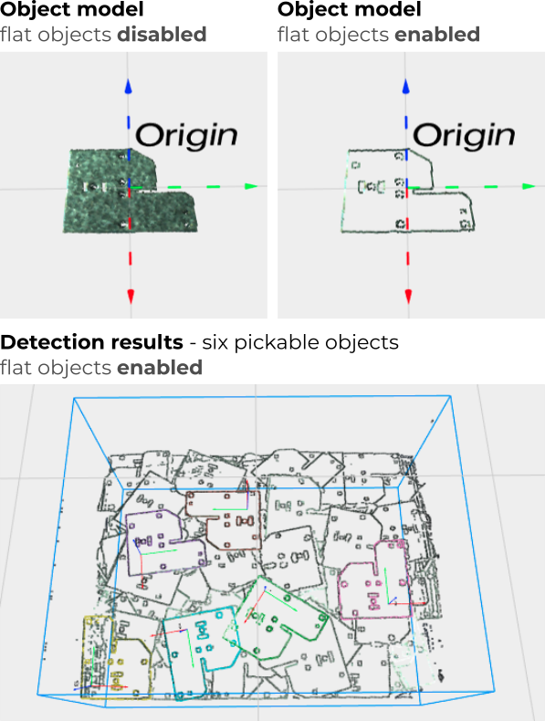
The flat objects option tells Pickit Teach to focus on shape edges when performing object detection. The following example shows how to detect thin and flat sheet metal parts with this option.

Tip
When teaching from camera the model of a flat object, it is advised to have the model parallel to the ground (not tilted). For thin objects, it’s advised to raise them during teaching to have a clear height difference with respect to the ground plane.
Tip
When detecting very thin objects, it is advised to include the ground plane when building the ROI. This makes sure that objects lying directly on the ground are completely included in the ROI.
Note that, for non-thin objects, it is generally advised to exclude the ground plane from the ROI for performance reasons. When the flat objects option is enabled, the ground plane doesn’t add a significant performance overhead, as only its edges are considered.