How to have faster cycle times?

For a vision-based application to be a success, parts not only need to be detected and picked reliably, but cycle time requirements must also be satisfied. These requirements can be the result of technical specifications, such as the expected feed rate in a machine tending application. They can also result from business constraints, such as the expected return of investment time for the robot cell.

Cycle time refers to the time spent performing a full cycle of the application, such as a full pick and place sequence. This article focuses on how to optimize the cycle time of an application that is already picking reliably. It focuses on these main strategies to reduce cycle time:

By taking these strategies into account, cycle time can be reduced significantly, from an unoptimized sequence such as this one:

Unoptimized sequential timeline: vision capture and process, then the robot picks and places the part from the current detection, repeating until no more pickable parts, after which this pick station is refilled

to an optimized and parallelized execution such as this one:
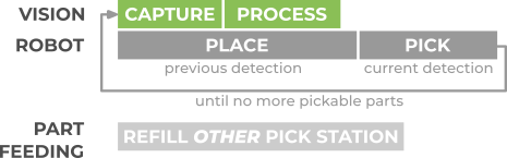
Optimized timeline: vision capture and processing run while the robot places the part from the previous detection, then picks from the current detection, repeating until no more pickable parts, while the other pick station is refilled

The following sections describe each of the strategies in more detail.

Mask object detection time with robot motions

Probably the most significant (and easy) cycle time optimization for a vision-guided picking application is to eliminate or minimize the amount of time a robot is idle, waiting for detection results to be ready. Ideally, the robot should be busy at all times, picking or placing parts.

To this end, the idea is to perform object detection in parallel to the placing motion:

  • Go to the pick point produced by the previous detection run (below, top left).

  • Pick the part, go to the Detect point and trigger a new detection (below, top right). Learn more about what constitutes a good detection point and camera location here.

  • Perform the placing motion in parallel to object detection (below, bottom left). Typically, object detection completes before the placing motion, fully masking the detection time. Learn more about how to have faster detections here.

  • The next part to be picked is ready to be sent to the robot (below, bottom right).
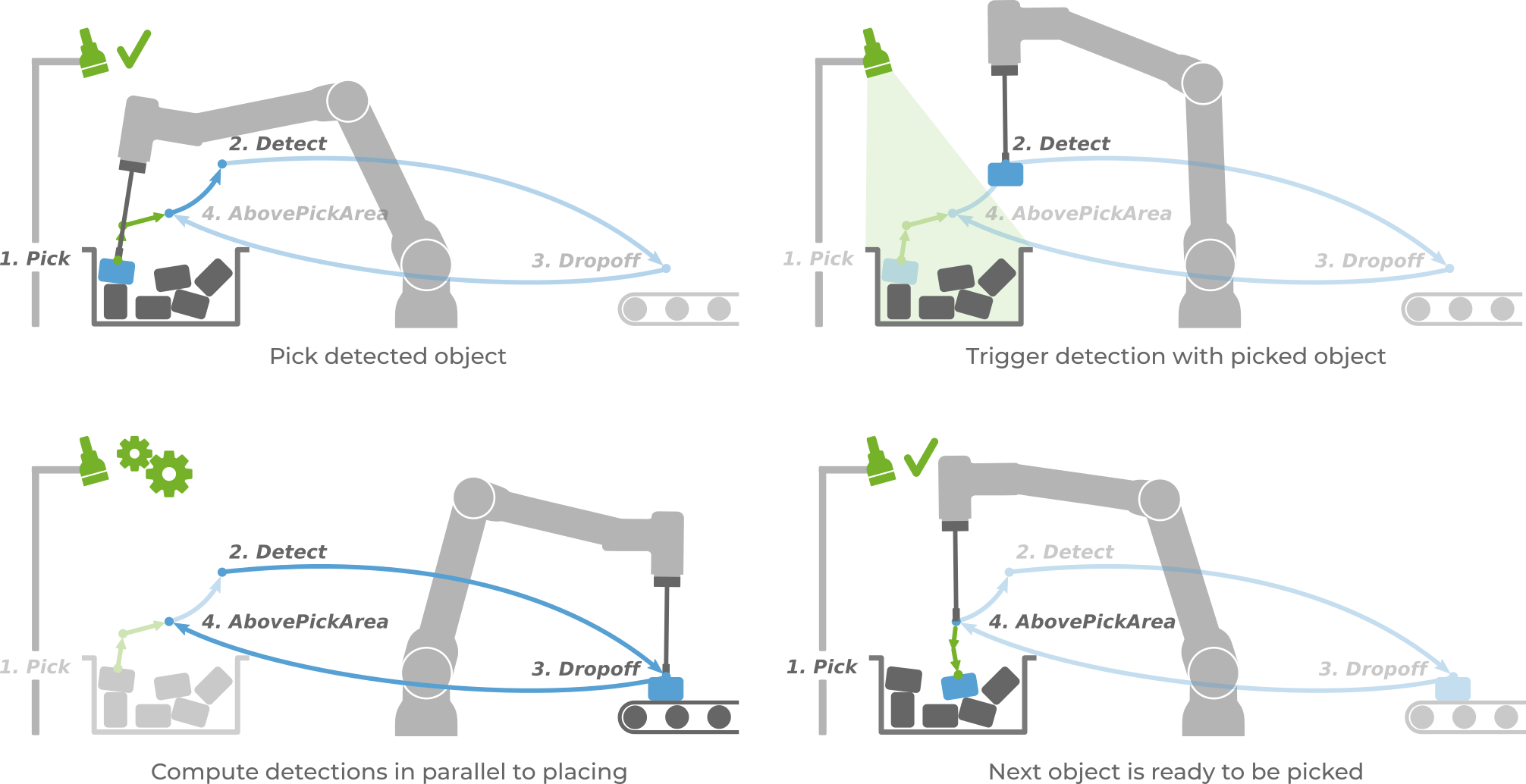
Four-step cycle with a fixed camera: pick the detected object, move to the Detect point and trigger detection with the picked object, compute detections in parallel to placing at the Dropoff, and the next object is ready to be picked from AbovePickArea

On a timeline, the parallel execution of the placing motion and object detection is depicted below. The above sequence starts in the PICK state of one cycle and ends in the PICK state of the next cycle:
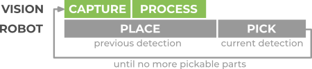
Timeline with a fixed camera: vision capture and processing run in parallel with the robot placing the part from the previous detection, followed by picking from the current detection, repeating until no more pickable parts

The robot-independent bin picking program describes how to write a program that masks object detection time. Additionally, example picking programs shipped by Pickit robot integrations have this optimization already built-in.

Robot-mounted cameras

When the camera is mounted on the robot, detection time cannot be fully masked by robot motions. Object detection consists of two steps, image capture and image processing. During image capture, the robot must remain stationary in the Detect point, so only the image processing time can be masked with robot motions.

Timeline with a robot-mounted camera: the robot waits during image capture, then image processing runs in parallel with placing the part from the previous detection, followed by picking from the current detection

Learn more on optimizing image capture time here, and how this affects the robot program logic here. Also, read the next section on picking multiple objects per detection run for an additional optimization that applies to some applications.

Note that, to mask detection time, image capture needs to be performed with a picked object. This means that the camera view should not be blocked by the picked object for the optimization to be applicable.
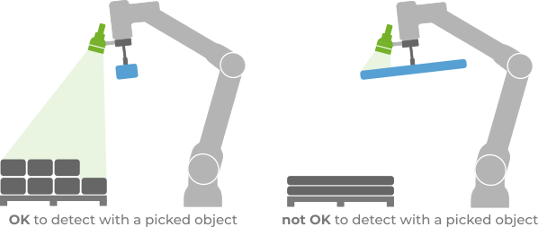
Robot-mounted camera capturing with a picked object: a small part is OK as it doesn't block the camera view of the pallet, a long part is not OK as it blocks the view

Picking multiple objects per detection run

There are two situations in which detection time cannot be fully masked with robot motions:

  • The camera is robot-mounted, and the image capture time is not masked.

  • The placing motion is very short, and ends up being faster than the object detection time.

One way to reduce this impact to a fraction is to pick more than one object per detection run. This is only applicable to situations where picking one part doesn’t disturb much the location of neighboring parts. This is the case, for example, when parts are presented in a semi-structured way, such as in depalletizing, where the robot can pick all detections in a layer.

In the below example, if there are three parts per layer and Pickit finds them all, the unmasked image capture time is spread over three picks instead of just one.
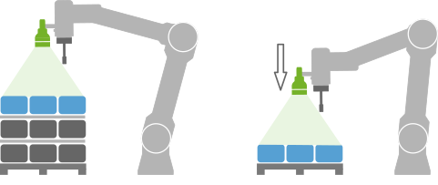
Robot-mounted camera above a high pallet stack: as layers are removed, the robot moves the detection pose down to keep the top layer within the camera depth range

The pickit_next_object() function should be used in your robot program to request the next detected object from Pickit without triggering a new detection.

Tip

Picking multiple objects per detection run is applicable beyond semi-structured part layouts. If a bin picking application is such that the disturbance of picking a part is localized to its immediate vicinity, you can enable the Objects distance filter, which only allows picking objects that are at least a certain distance apart. In the example below, the orange object is detected, but is marked as unpickable for being too close to object 1, as its location can be disturbed when 1 is picked.
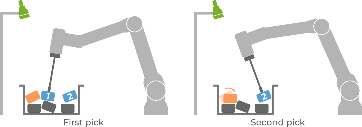
Objects distance filter: in the first pick the robot picks object 1, and an orange object close to it is unpickable; in the second pick the orange object has shifted and the robot picks object 2, which is far enough away

This filter is an advanced setting, and needs to be enabled by going to Settings > Advanced settings > Enable advanced picking settings. It shows up in the Pick strategy section of the Picking page.

Mask part feeding time with picking

In some applications, feeding new parts to pick is a process that can take a non-negligible amount of time, such as when an empty bin or pallet needs to be refilled or replaced. To not interrupt part picking during the feeding process, it is recommended to use multiple picking stations.
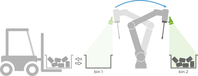
Robot-mounted camera switching from an empty bin 1, which a forklift replaces, to picking from a full bin 2

On a timeline, the parallel execution of part picking in one station and part feeding in another is depicted below:

Optimized timeline: vision capture and processing run while the robot places the part from the previous detection, then picks from the current detection, repeating until no more pickable parts, while the other pick station is refilled

Minimize the time spent in robot motions

This section covers a number of general recommendations that are independent of the usage of a vision system, as well as a few ways in which Pickit can explicitly contribute to faster robot motions.

Minimize path lengths

A proper placement of the elements in your robot cell can reduce the distances travelled by the robot tool, hence the time it takes to traverse them. This includes the location of the robot, the bin or pallet, the dropoff location, and intermediate stations (if applicable). By “location” we refer not only to the position in the ground, but also to consider using raisers for the robot and/or bin, if required.
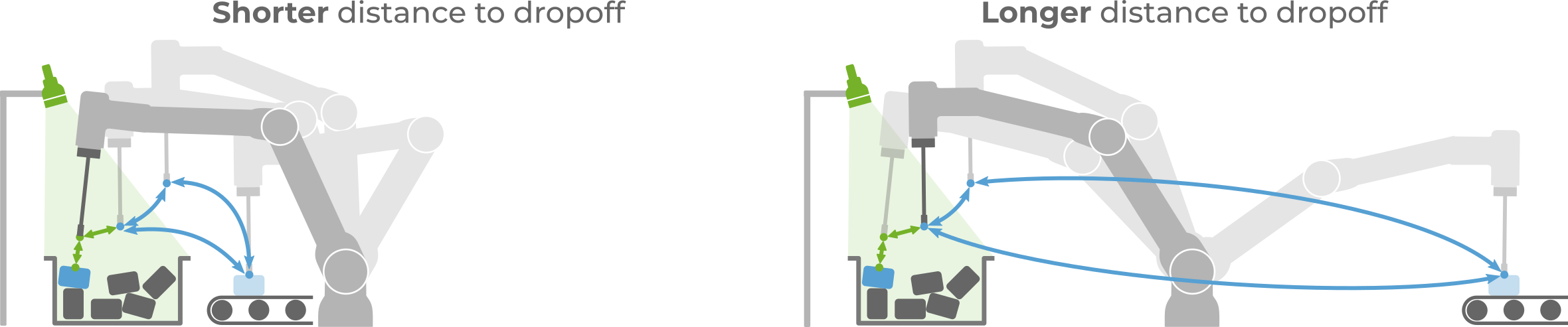
Robot cell layouts compared: a dropoff conveyor placed close to the bin gives a shorter distance to dropoff than one placed on the far side of the robot

Set adequate velocity and acceleration limits

Most robot programming languages allow to specify maximum velocities and accelerations to use for reaching waypoints. In a picking application, it’s typically desired to use:

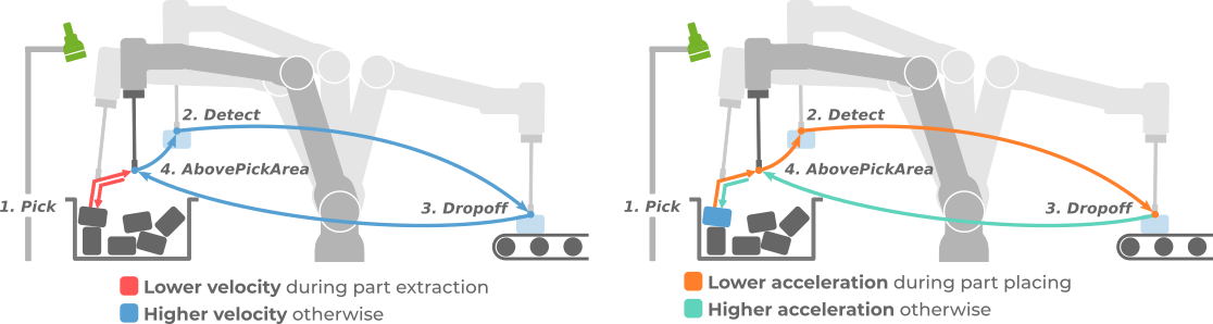
  • Lower velocities during part extraction, higher velocities otherwise. Part extraction is normally the only unstructured part of an application, where pick locations are not known in advance. Lower velocities help to better respond to (and recover from) unexpected collisions with the environment without harming the equipment. Also, prefer linear TCP movements for part extraction, and joint-space motions for large free-space displacements.

  • Lower accelerations during part placing, higher accelerations otherwise. Moving the robot with too high accelerations can cause the tool to loose its grasp on a part and drop it before reaching the dropoff location.

    Pick and place path with Pick, Detect, AbovePickArea and Dropoff waypoints: lower velocity during part extraction and higher velocity otherwise; lower acceleration during part placing and higher acceleration otherwise

What constitutes a low or high velocity/acceleration is application-dependent, but regardless of the values, it can be seen that the limits do not apply equally to all waypoints in a pick and place application.

Use blending on waypoints that don’t need stopping

In a picking application, some waypoints should be reached by the robot with zero velocity. Normally, this refers to the Pick and Dropoff points (also Detect if the camera is robot-mounted). In more complex applications, it may include other points such as intermediate stations for re-grasping or performing quality control checks.

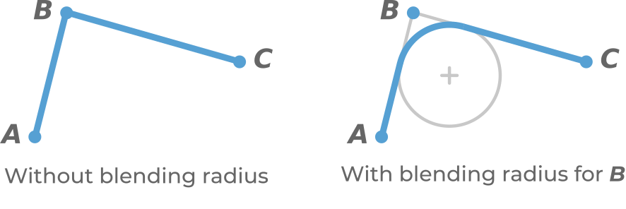
Other waypoints don’t require stopping at them, nor reaching them with exact position. Blending is a feature supported by most robot programming languages where the robot smoothly transitions between two trajectories, preventing unnecessary decelerations/accelerations. Blending is typically implemented with circular segments.

Robot path through waypoints A, B and C: without blending radius the path has a sharp corner at B, with a blending radius for B the corner is replaced by a smooth arc

Prepare the gripper before reaching the pick point

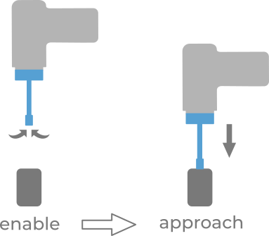
Some grippers require some preparation before performing a grasp. Suction grippers, for instance, need to be enabled for some time to build up vacuum.

This preparation can be done in parallel to the last approach motion, such that when the pick point is reached, the gripper is ready.

Suction tool vacuum is enabled before the final approach motion to the part, so the gripper is ready when the pick point is reached

Select a good robot tool for your application

Proper robot tool selection can constribute to faster cycle times in the following ways:

  • Higher pick success rate: More successful picks, less dropped parts and pick retries.

  • Less robot motions required to perform a pick, especially if the tool has flexible pick orientation.

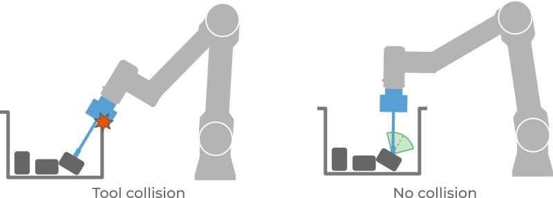
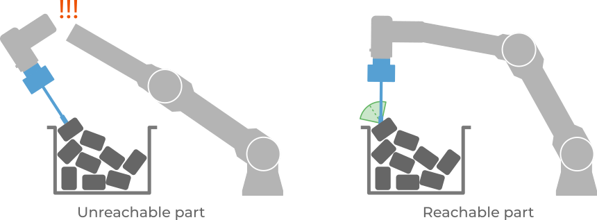
In the example below, note how adding tilt flexibility produces more pickable parts, and less robot flange tilting.

Tilted part near the bin wall: picking along the part's nominal orientation makes the tool collide with the bin, while flexible pick orientation lets the tool pick it vertically with no collision Tilted part in a bin: picking along its nominal orientation is unreachable for the robot, while flexible pick orientation lets the robot pick it from a reachable, more vertical pose

Refer to the article on what makes a good robot tool for bin picking to learn more.

Furthermore, if the robot tool has the means to measure pick success, cycle time can be optimized by skipping the place motion on pick failure, and instead proceed to trigger a new object detection. The robot-independent pick and place program exemplifies how to implement this.

Exploit the desired pick orientation

A detected object can have multiple ways of being picked (learn more). When this is the case, a good choice of desired pick orientation can result in less robot motions.

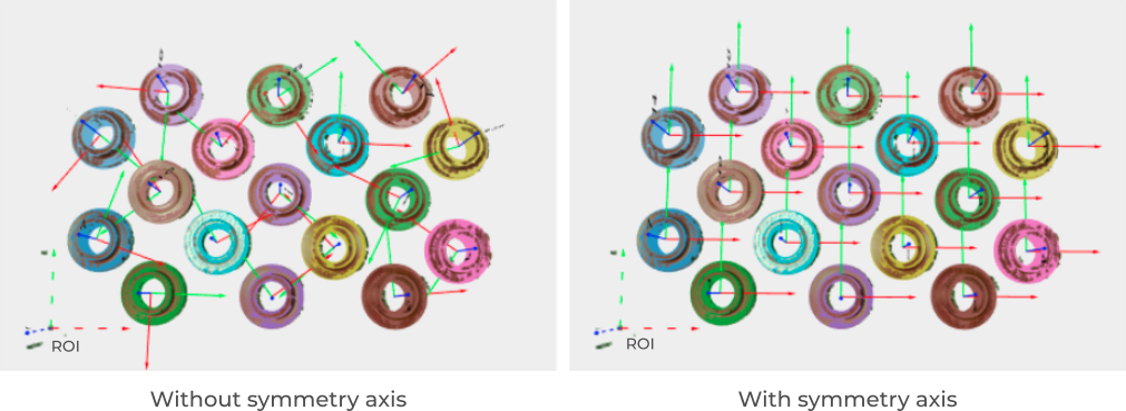
Consider the example of the ring parts shown below. If the pick point is made to be symmetric about the part axis, it’s possible to pick the parts in a way that the desired pick orientation is satisfied.

Detected ring parts in the 3D view: without a symmetry axis the pick frames point in random directions, with a symmetry axis they are all aligned to the same desired pick orientation

Unnecessary motion of the last robot joint is minimized when the AbovePickArea waypoint also matches the desired pick orientation.

Robot above a bin with the AbovePickArea waypoint matching the desired pick orientation, so the tool moves straight down to the Pick point without rotating the last joint